ENGINE PERFORMANCE
4.0L
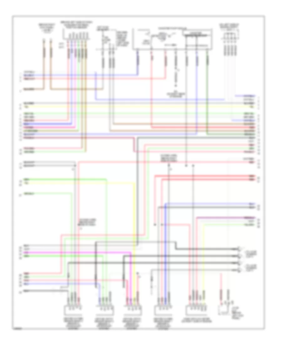
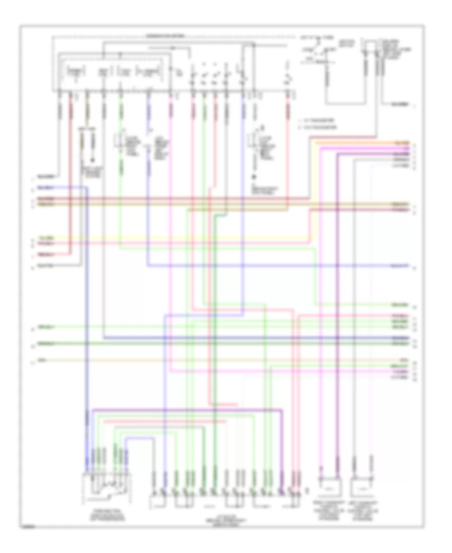
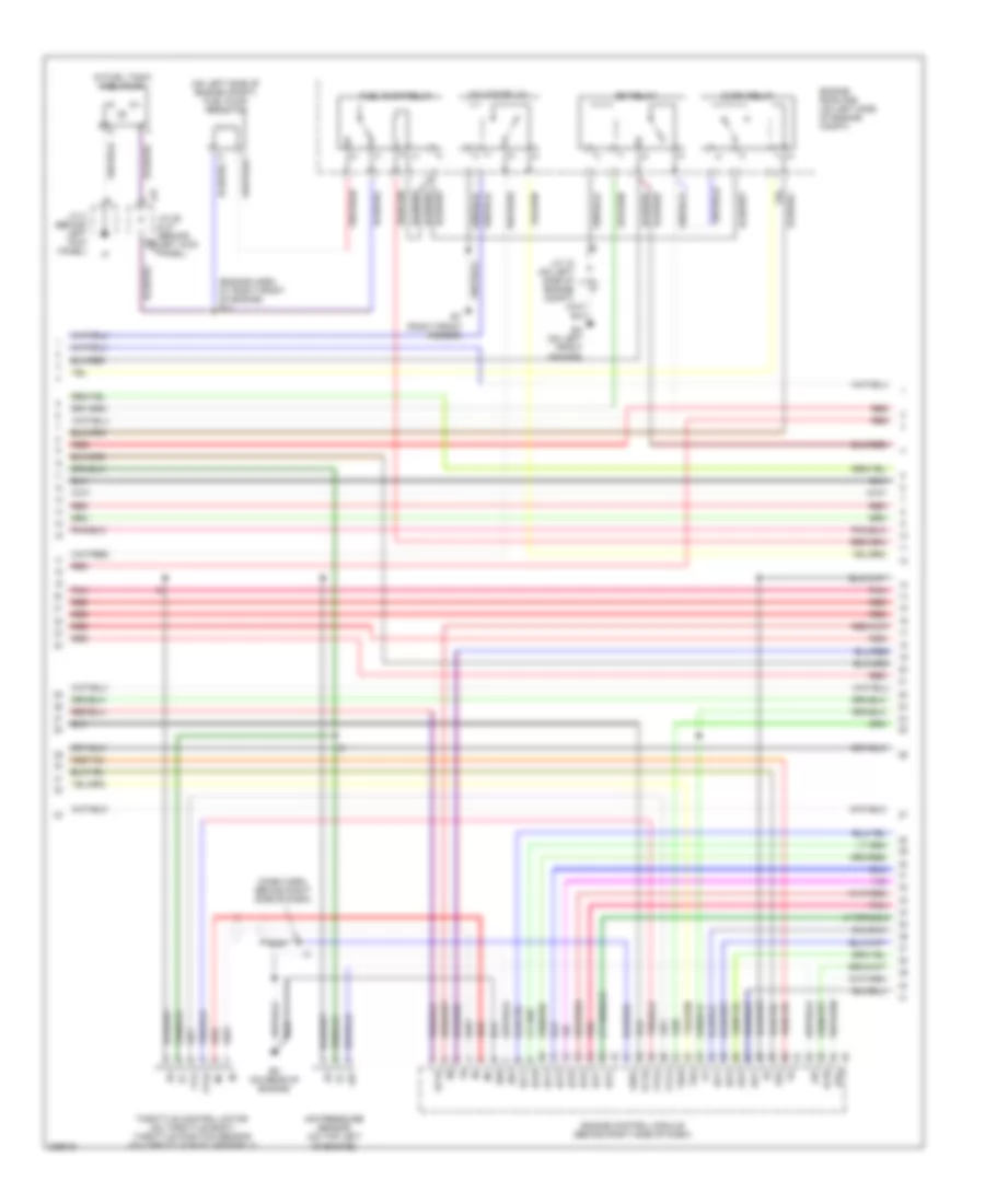
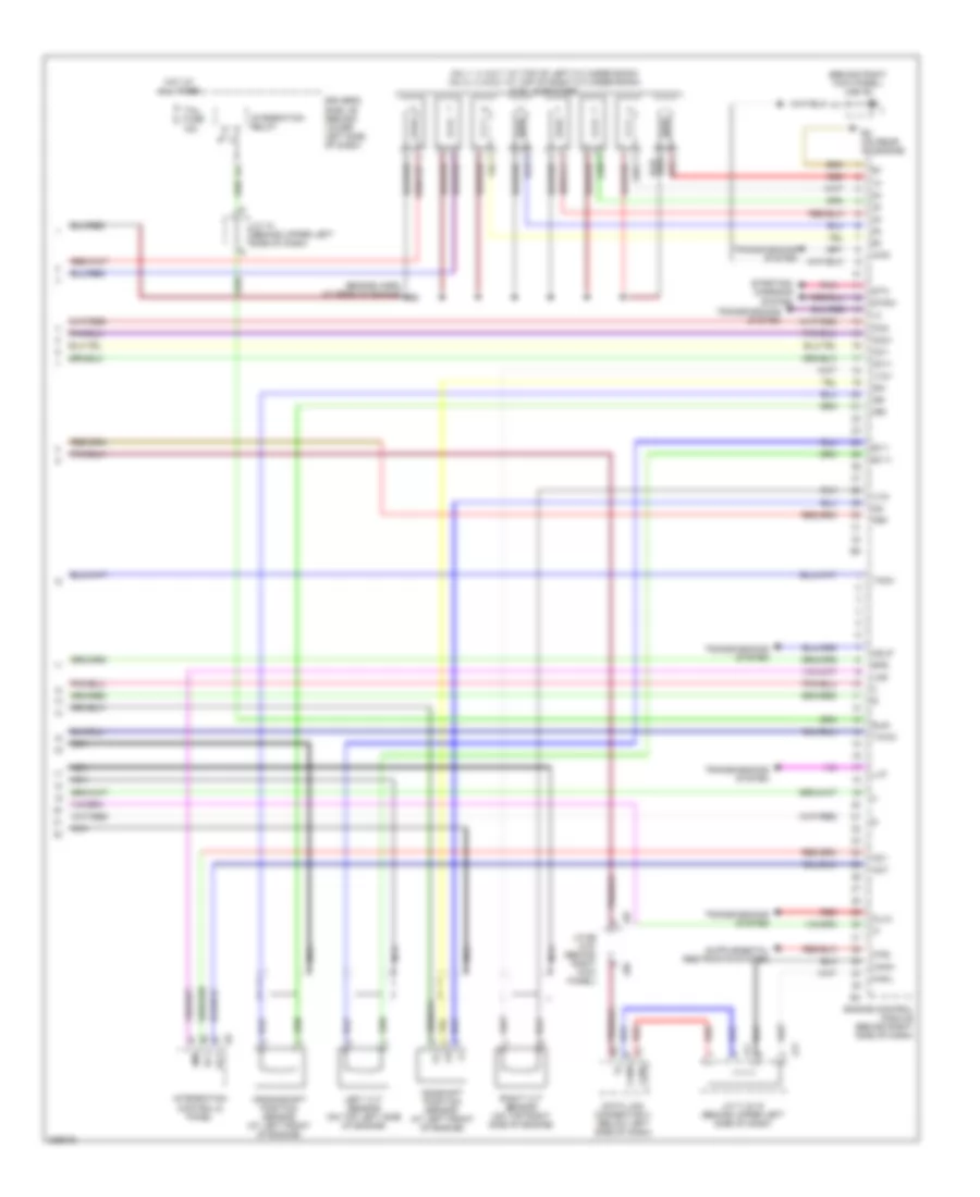
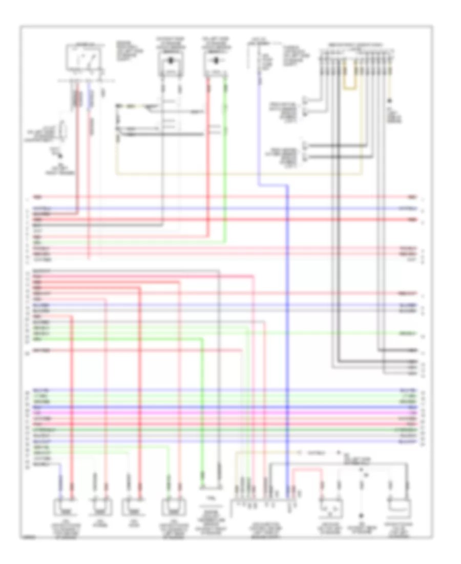
4.0L, Engine Performance Wiring Diagram (1 of 7) for Toyota Tundra 2006

List of elements for 4.0L, Engine Performance Wiring Diagram (1 of 7) for Toyota Tundra 2006:
- (in dash harn, behind upper right side of dash)
- (inside transmission) electronically controlled transmission solenoid
- (on left side of engine) ev
- (on right rear of engine) eu
- +b2
- +bm
- A1a+
- A1a-
- A2a+
- A2a-
- Accr
- Batt
- Cruise control system
- E03
- E04
- E05
- Ekn2
- Eknk
- Engine control module (behind right side of dash)
- Epa
- Epa2
- Ha1a
- Ha2a
- Ht2b
- Igsw
- J/c 26 & 27 (behind left kick panel)
- J26
- J27
- Knk1
- Knk2
- Me01
- Mpmp
- Mrel
- Nsw
- Nt+
- Nt-
- O/d direct clutch speed sensor
- Odms
- Ox2b
- Pnk
- Power distribution system
- Ppmp
- Red
- Sl1
- Sl1+
- Sl1-
- Sl2
- Sl2+
- Sl2-
- Slt
- Slt+
- Slt-
- Slu
- Slu+
- Slu-
- Sp2+
- Sp2-
- Starting/ charging system
- Stp
- Th02
- Tho1
- Trans- missions system
- Vcp2
- Vcpa
- Vehicle speed sensor (electronically controlled transmission) (on transmission)
- Vpa
- Vpa2
- Vpmp
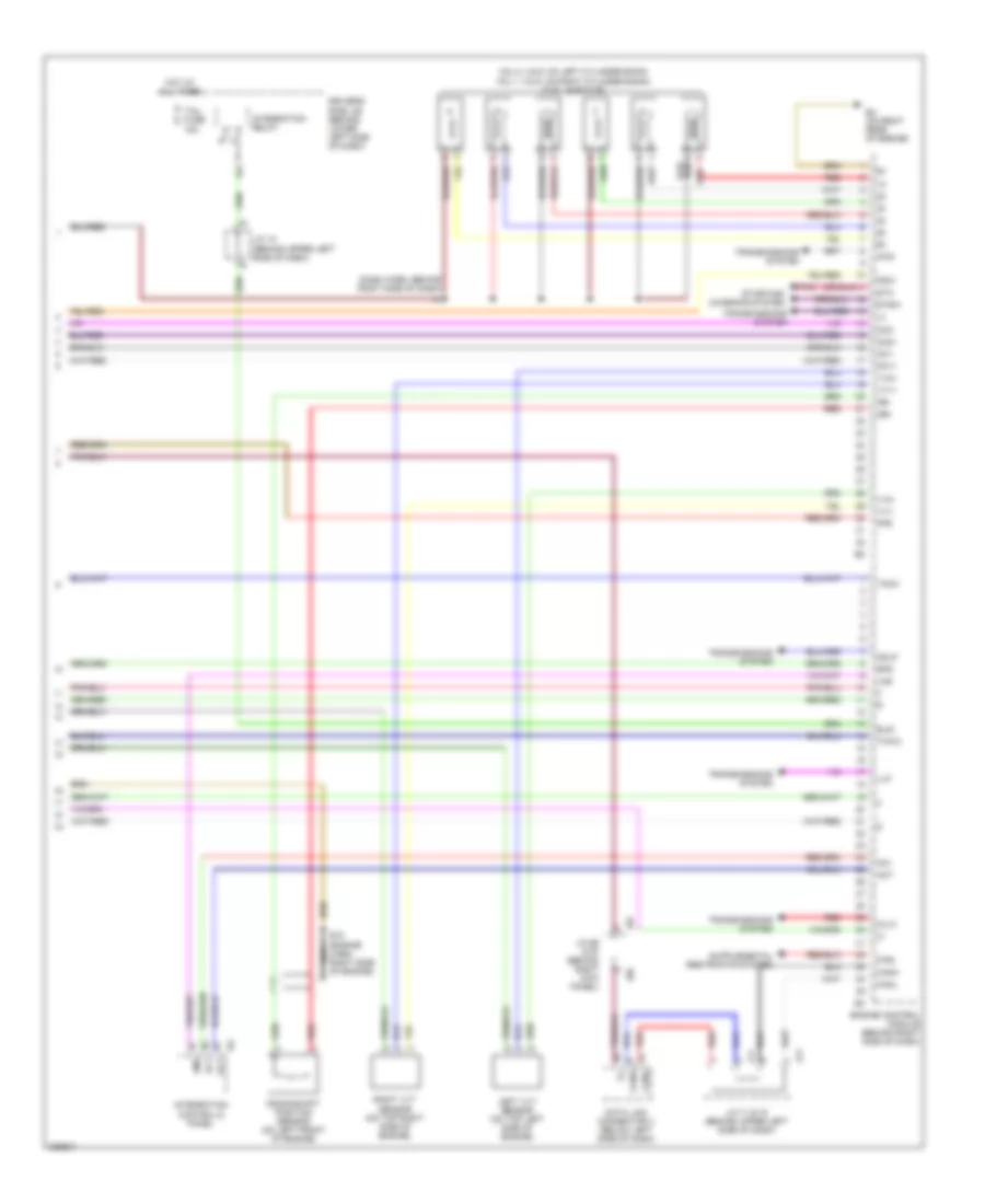
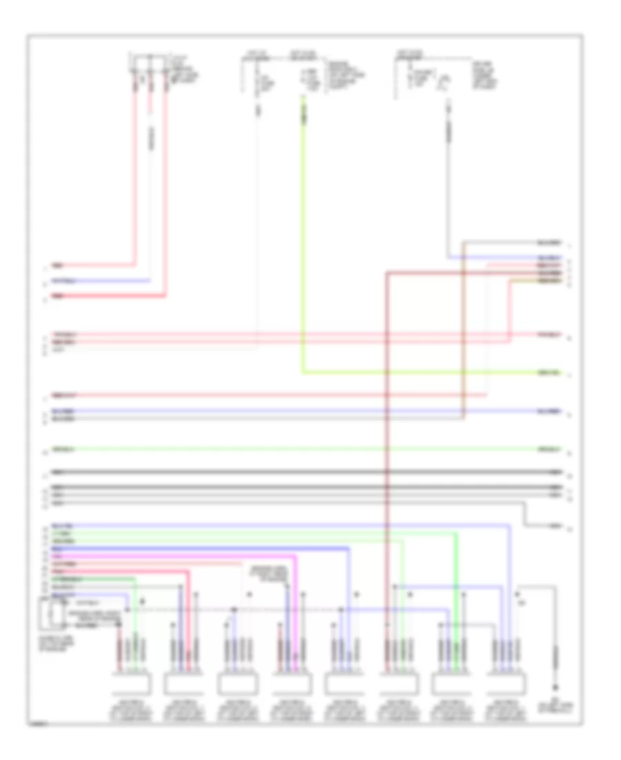
4.0L, Engine Performance Wiring Diagram (2 of 7) for Toyota Tundra 2006
List of elements for 4.0L, Engine Performance Wiring Diagram (2 of 7) for Toyota Tundra 2006:
- (a/t)
- (behind left side of dash) accelerator pedal position sensor
- (behind right kick panel) j/c 66
- (in dash harn, behind right side of dash)
- (m/t)
- (on left side of engine compt) j/c 1
- Af+
- Af-
- Air fuel ratio sensor (bank 1 sensor 1) (on exhaust system)
- Air fuel ratio sensor (bank 2 sensor 1) (on exhaust system)
- Canister pressure sensor
- Canister pump module
- Driver's side j/b (behind lower left side of dash)
- E2g
- Epa
- Epa2
- Eu (on right rear of engine)
- F10
- F11
- Heated oxygen sensor (bank 1 sensor 2) (on exhaust system)
- Heated oxygen sensor (bank 2 sensor 2) (on exhaust system)
- Hot in on or start
- Ign fuse 5a
- J26 j/c 26 & 27 (behind left kick panel)
- J27
- Leak detection pump
- Mass air flow meter (on right side of engine)
- Nca
- Nca a
- Nca b
- Nca c
- Nca d
- Pnk
- Red
- Tha
- To j/c 65 (diagram 4 of 7)
- Vcp2
- Vcpa
- Vent valve
- Vpa
- Vpa2
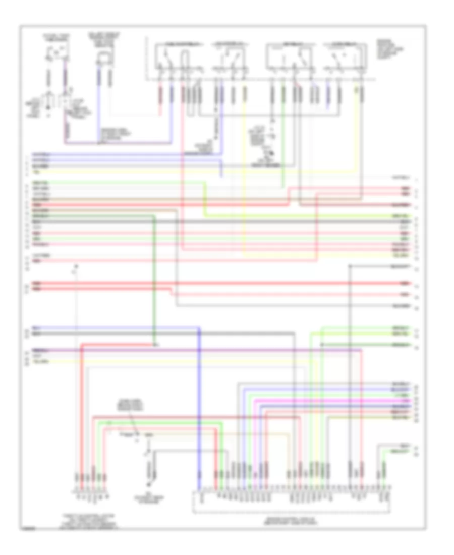
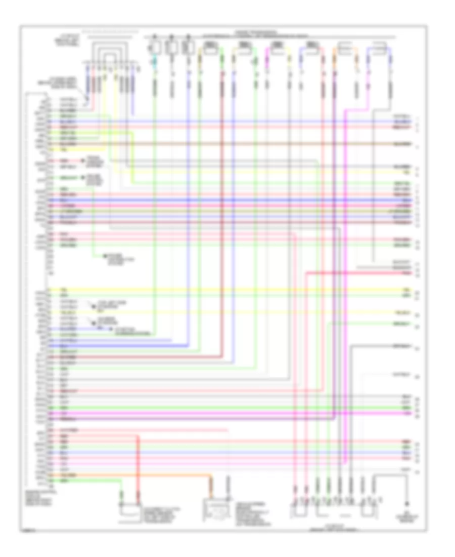
4.0L, Engine Performance Wiring Diagram (3 of 7) for Toyota Tundra 2006
List of elements for 4.0L, Engine Performance Wiring Diagram (3 of 7) for Toyota Tundra 2006:
- (dash harn, behind right side of dash)
- (engine harn, at right front of engine) e11
- (in fuel tank) fuel pump
- (on left side of engine compt) fuel pump resistor
- A/f htr relay
- Acis
- C/opn relay
- E01
- E02
- E2g
- Ea (on left front fender)
- Efi relay
- Engine control module (behind right side of dash)
- Engine room r/b (on left side of engine compt)
- Et (on right side of engine compt)
- Eu (on right rear of engine)
- Fuel pump relay
- Ge01
- Ht1b
- Igf1
- Igt1
- Igt2
- Igt3
- Igt4
- Igt5
- Igt6
- J/c 18 (on left side of engine compt)
- J/c 26 & 27 (behind left kick panel)
- J/c 3 (behind left kick panel)
- J26
- J27
- Nca
- Ox1b
- Prg
- Red
- Tha
- Throttle control motor (on throttle body) throttle position sensor (on throttle body assembly)
- Thw
- Vta
- Vta1
- Vta2
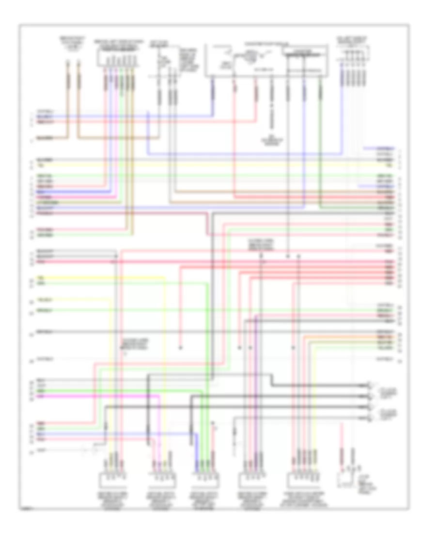
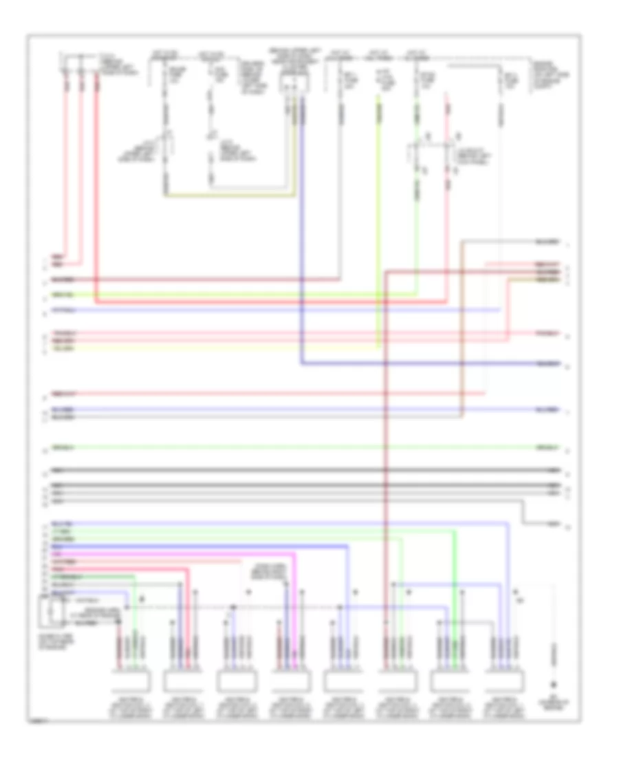
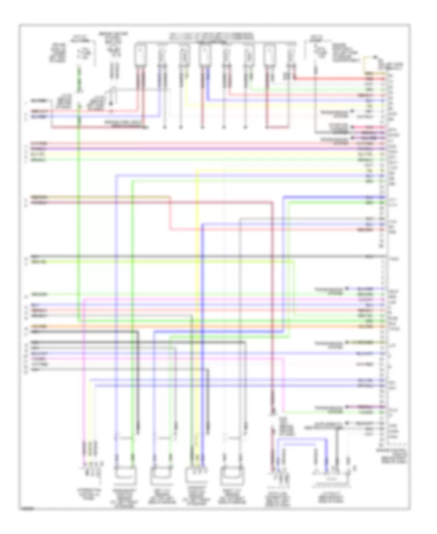
4.0L, Engine Performance Wiring Diagram (4 of 7) for Toyota Tundra 2006
List of elements for 4.0L, Engine Performance Wiring Diagram (4 of 7) for Toyota Tundra 2006:
- (behind upper right side of dash) j/c 65
- (engine harn, at front of engine)
- (on top left
- (on top right
- E14 (engine harn, at rear of engine)
- E17
- Engine coolant temperature sensor (at right rear of engine)
- Ev (on left side of engine)
- From air fuel ratio sensor shields (diagram 2 of 7)
- From heated oxygen sensor shields (diagram 2 of 7)
- Nca
- Power steering oil pressure switch (on right front of engine)
- Red
- Side of engine) knock sensor (bank 1)
- Side of engine) knock sensor (bank 2)
- Vsv (acis)
- Vsv (purge)
4.0L, Engine Performance Wiring Diagram (5 of 7) for Toyota Tundra 2006
List of elements for 4.0L, Engine Performance Wiring Diagram (5 of 7) for Toyota Tundra 2006:
- (behind upper left side of dash) diode (a/t)
- (engine harn, at rear of engine) e14
- A red
- A/f htr fuse 20a
- Acc fuse 15a
- Driver's side j/b (behind lower left side of dash)
- E14
- E15 (engine harn, right front of engine)
- Efi 1 fuse 20a
- Efi 2 fuse 10a
- Engine room r/b (on left side of engine compt)
- Etcs fuse 10a
- Ev (on left side of engine)
- G11
- Gauge fuse 10a
- Hot at all times
- Hot in on or acc
- Hot in on or start
- Igniter & ignition coil 1 (at top of right cylinder bank)
- Igniter & ignition coil 2 (at top of left cylinder bank)
- Igniter & ignition coil 3 (at top of right cylinder bank)
- Igniter & ignition coil 4 (at top of left cylinder bank)
- Igniter & ignition coil 5 (at top of right cylinder bank)
- Igniter & ignition coil 6 (at top of left cylinder bank)
- J/c 28 & 29 (behind upper right side of dash)
- J/c 8 (behind upper left side of dash)
- J/c 8 (behind upper left side of dash) a red
- J/c 9 (behind upper left side of dash)
- J26
- J26 j/c 26 & 27 (behind left kick panel)
- J27
- J28
- J29
- Noise filter (on top rear of engine)
- Red
- Vehicle speed sensor (combination meter) (m/t) (on transmission)
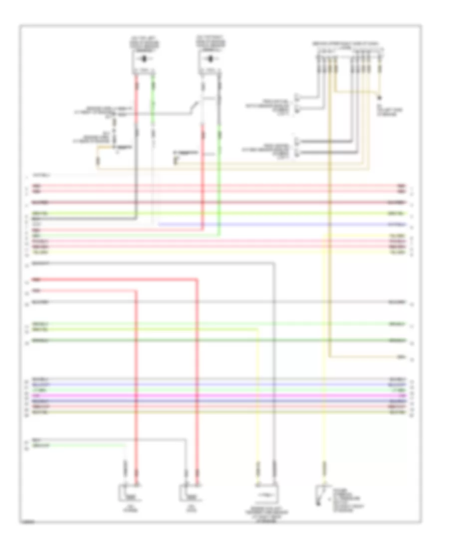
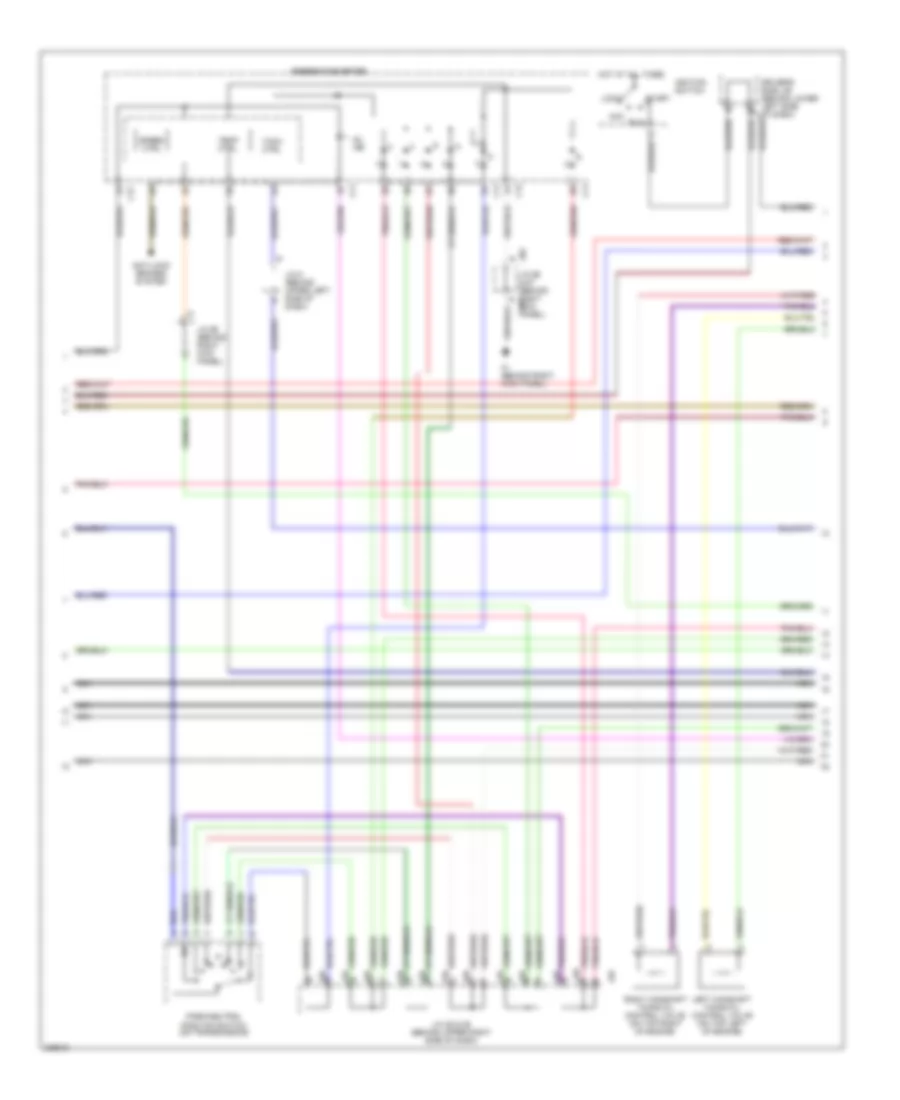
4.0L, Engine Performance Wiring Diagram (6 of 7) for Toyota Tundra 2006
List of elements for 4.0L, Engine Performance Wiring Diagram (6 of 7) for Toyota Tundra 2006:
- A j28
- A/t
- Acc
- Anti-lock brakes system
- B j28
- C j28
- C11
- C12
- Combination meter
- D j28
- Driver's side j/b (behind lower left side of dash)
- F j28
- G j28
- Hot at all times
- Ignition switch
- Ih (behind right kick panel)
- J/c 28 & 29 (behind upper right side of dash)
- J/c 5 (behind upper left side of dash)
- J/c 66 (behind right kick panel)
- J29
- J66 j/c 66 & 67 (behind right kick panel) j67
- Left camshaft timing oil control valve (top left of engine)
- Lock
- M/t
- Mil ind
- Oil press ctrl
- Park/neutral position switch (on transmission)
- Right camshaft timing oil control valve (top right of engine)
- Run
- Speed ctrl
- Start
- Tach ctrl
- Temp ctrl
- W/ tachometer
- W/o tachometer
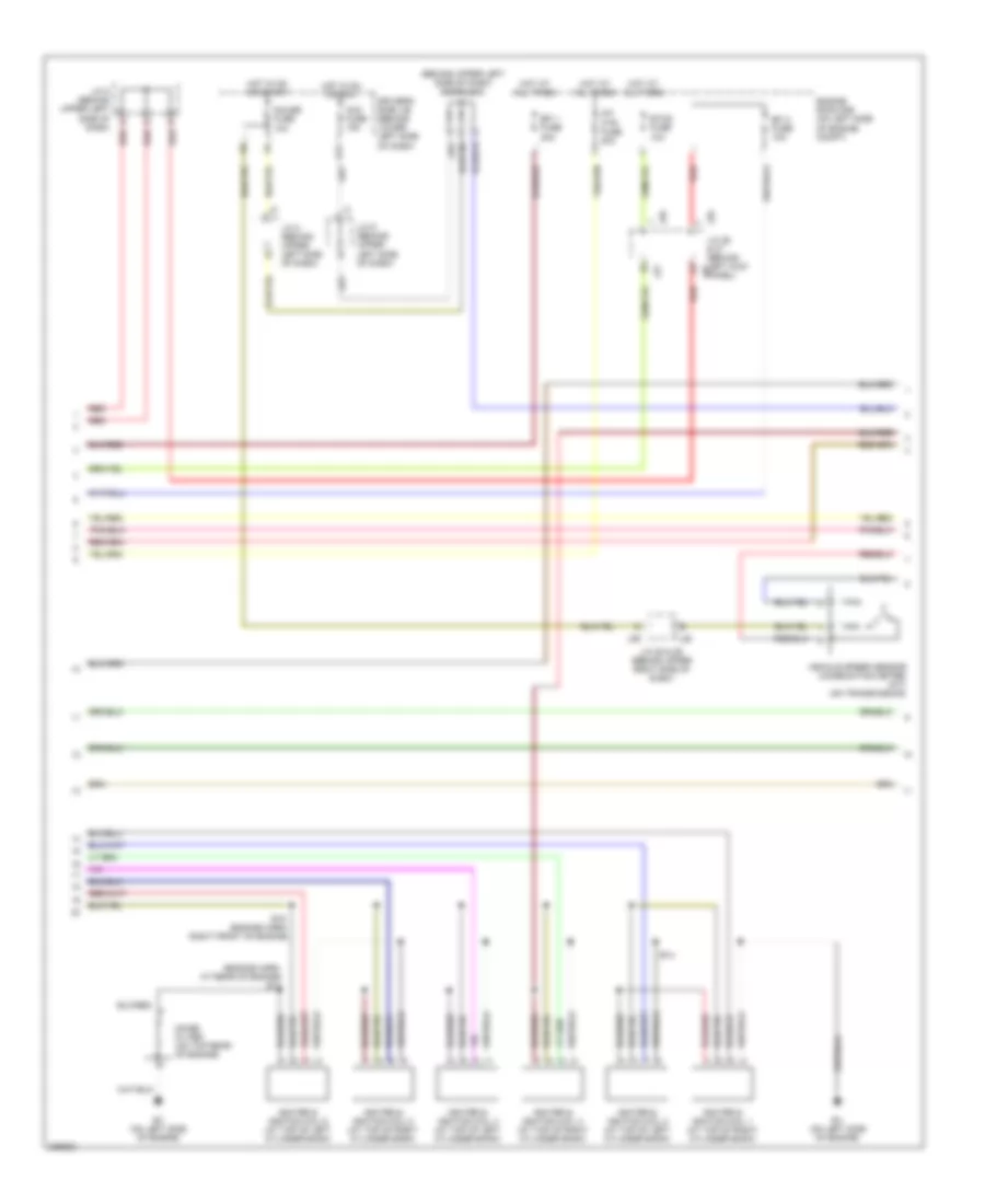
4.0L, Engine Performance Wiring Diagram (7 of 7) for Toyota Tundra 2006
List of elements for 4.0L, Engine Performance Wiring Diagram (7 of 7) for Toyota Tundra 2006:
- (dash harn, behind right side of dash)
- (inj 2, 4 & 6: on left cylinder bank) (inj 1, 3 & 5: on right cylinder bank) fuel injector
- 4wd
- Ac1
- Act
- Canh
- Canl
- Crankshaft position sensor (on left front of engine)
- Data link connector 3 (below left side of dash)
- Driver's side j/b (behind lower left side of dash)
- E18 (engine harn, right side nca
- Elsi
- Engine control module (behind right side of dash)
- Eu (on right rear of engine)
- F/ps
- Fpr
- Hot at all times
- I24
- Integration control & panel
- Integration relay
- J/c 10 (behind upper left side of dash)
- J/c 66 & 67 (behind right kick panel)
- J/c 71 & 72 (behind upper left side of dash)
- J66
- J67
- J71
- J72
- Left vvt sensor (on top left side of engine)
- Llp
- Lms
- Ne+
- Ne-
- Oc1+
- Oc1-
- Oc2+
- Oc2-
- Odlp
- Of engine)
- Oilw
- Pnk
- Psw
- Red
- Right vvt sensor (on top right side of engine)
- Spd
- Sta
- Starting/ charging system
- Stsw
- Tach
- Tail fuse 15a
- Thwo
- Transmissions system
- Vv1+
- Vv1-
- Vv2+
- Vv2-
4.7L
4.7L, Engine Performance Wiring Diagram, Access/Standard Cab (1 of 7) for Toyota Tundra 2006
List of elements for 4.7L, Engine Performance Wiring Diagram, Access/Standard Cab (1 of 7) for Toyota Tundra 2006:
- (in dash harn, behind upper right side of dash)
- (inside transmission) electronically controlled transmission solenoid
- (on rear of engine) ec
- (top left side of engine) ew
- +b2
- +bm
- A1a+
- A1a-
- A2a+
- A2a-
- Accr
- Aidi
- Airp
- Airv
- Batt
- Cruise control system
- E03
- E04
- E05
- Ec (on rear of engine)
- Ekn2
- Eknk
- Engine control module (behind right side of dash)
- Epa
- Epa2
- Ha1a
- Ha2a
- Ht2b
- Igsw
- J/c 26 & 27 (behind left kick panel)
- J26
- J27
- Knk1
- Knk2
- Me01
- Mpmp
- Mrel
- Nsw
- Nt+
- Nt-
- O/d direct clutch speed sensor (on left side of transmission)
- Odms
- Ox2b
- Pnk
- Power distribution system
- Ppmp
- Red
- Sl1
- Sl1+
- Sl1-
- Sl2
- Sl2+
- Sl2-
- Slt
- Slt+
- Slt-
- Slu
- Slu+
- Slu-
- Sp2+
- Sp2-
- Starting/ charging system
- Stp
- Th02
- Tho1
- Trans- missions system
- Vcp2
- Vcpa
- Vehicle speed sensor (electronically controlled transmission) (on transmission)
- Vpa
- Vpa2
- Vpmp
4.7L, Engine Performance Wiring Diagram, Access/Standard Cab (2 of 7) for Toyota Tundra 2006
List of elements for 4.7L, Engine Performance Wiring Diagram, Access/Standard Cab (2 of 7) for Toyota Tundra 2006:
- (behind left side of dash) accelerator pedal position sensor
- (behind right kick panel) j/c 66
- (in dash harn, behind right side of dash)
- (on left side of engine compt) j/c 1
- Af+
- Af-
- Air fuel ratio sensor (bank 1 sensor 1) (on top left of engine)
- Air fuel ratio sensor (bank 2 sensor 1) (on exhaust system)
- Canister pressure sensor
- Canister pump module
- Driver's side j/b (behind lower left side of dash)
- E2g
- Ec (on rear of engine)
- Epa
- Epa2
- F10
- F11
- Heated oxygen sensor (bank 1 sensor 2) (on exhaust system)
- Heated oxygen sensor (bank 2 sensor 2) (on exhaust system)
- Hot in on or start
- Ign fuse 5a
- J26 j/c 26 & 27 (behind left kick panel)
- J27
- Leak detection pump
- Mass air flow meter (on right side of engine compartment, on air cleaner housing)
- Nca
- Nca a
- Nca b
- Nca c
- Nca d
- Pnk
- Red
- Tha
- To j/c 64 (diagram 4 of 7)
- Vcp2
- Vcpa
- Vent valve
- Vpa
- Vpa2
4.7L, Engine Performance Wiring Diagram, Access/Standard Cab (3 of 7) for Toyota Tundra 2006
List of elements for 4.7L, Engine Performance Wiring Diagram, Access/Standard Cab (3 of 7) for Toyota Tundra 2006:
- (dash harn, behind right side of dash)
- (engine harn, at right front of engine) e11
- (in fuel tank) fuel pump
- (on left side of engine compt) fuel pump resistor
- A/f htr relay
- Acis
- Aip
- Air pressure sensor (on top left of engine)
- Aiv1
- Aiv2
- C/opn relay
- E01
- E02
- E2g
- Ea (on left front fender)
- Ec (on rear of engine)
- Efi relay
- Engine control module (behind right side of dash)
- Engine room r/b (on left side of engine compt)
- Et (right front fender)
- Fuel pump relay
- Ge01
- Ht1b
- Igf1
- Igf2
- Igt1
- Igt2
- Igt3
- Igt4
- Igt5
- Igt6
- Igt7
- Igt8
- J/c 18 (on left side of engine compt)
- J/c 26 & 27 (behind left kick panel)
- J/c 3 (behind left kick panel)
- J26
- J27
- Nca
- Ox1b
- Pnk
- Prg
- Red
- Tha
- Throttle control motor (on throttle body) throttle position sensor (on throttle body assembly)
- Thw
- Vta
- Vta1
- Vta2
4.7L, Engine Performance Wiring Diagram, Access/Standard Cab (4 of 7) for Toyota Tundra 2006
List of elements for 4.7L, Engine Performance Wiring Diagram, Access/Standard Cab (4 of 7) for Toyota Tundra 2006:
- (behind upper right side of dash) j/c 64
- (on left side
- (on right side
- A32
- A33
- Air injection control driver (left side of engine compt)
- Air pump (on top left of engine)
- Air switching valve (on top left of engine)
- Airp fuse 60a
- Batt
- E13
- Engine coolant temperature sensor (on right front of engine)
- Engine room r/b (on left side of engine compt)
- Ew (top left side of engine)
- Ex (on right rear of engine)
- From air fuel ratio sensor shields (diagram 2 of 7)
- From heated oxygen sensor shields (diagram 2 of 7)
- Hot at all times
- Nca
- Of engine) knock sensor (bank 1)
- Of engine) knock sensor (bank 2)
- Pnk
- Red
- Sip
- Siv
- Vsv (acis) (top left of engine)
- Vsv (air switching valve bank 1) (top center of engine)
- Vsv (air switching valve bank 2) (left rear of engine)
- Vsv (purge)
4.7L, Engine Performance Wiring Diagram, Access/Standard Cab (5 of 7) for Toyota Tundra 2006
List of elements for 4.7L, Engine Performance Wiring Diagram, Access/Standard Cab (5 of 7) for Toyota Tundra 2006:
- (behind upper left side of dash, near instrument cluster) diode (a/t)
- (dash harn, behind right side of dash) i3
- (engine harn, at rear of engine) e5
- A red
- A/f htr fuse 20a
- Acc fuse 15a
- Driver's side j/b (behind lower left side of dash)
- Ec (on rear of engine)
- Efi 1 fuse 20a
- Efi 2 fuse 10a
- Engine room r/b (on left side of engine compt)
- Etcs fuse 10a
- G11
- Gauge fuse 10a
- Hot at all times
- Hot in on or acc
- Hot in on or start
- Igniter & ignition coil 1 (at top of left cylinder bank)
- Igniter & ignition coil 2 (at top of right cylinder bank)
- Igniter & ignition coil 3 (at top of left cylinder bank)
- Igniter & ignition coil 4 (at top of right cylinder bank)
- Igniter & ignition coil 5 (at top of left cylinder bank)
- Igniter & ignition coil 6 (at top of right cylinder bank)
- Igniter & ignition coil 7 (at top of left cylinder bank)
- Igniter & ignition coil 8 (at top of right cylinder bank)
- J/c 8 (behind upper left side of dash)
- J/c 9 (behind upper left side of dash)
- J26
- J26 j/c 26 & 27 (behind left kick panel)
- J27
- Nca
- Noise filter (on top rear of engine)
- Pnk
- Red
4.7L, Engine Performance Wiring Diagram, Access/Standard Cab (6 of 7) for Toyota Tundra 2006
List of elements for 4.7L, Engine Performance Wiring Diagram, Access/Standard Cab (6 of 7) for Toyota Tundra 2006:
- A j28
- Acc
- Anti-lock brakes system
- B j28
- C j28
- C11
- C12
- Combination meter combination meter
- D j28
- Driver's side j/b (behind lower left side of dash)
- F j28
- G j28
- Hot at all times
- Ignition switch
- Ih (behind right kick panel)
- J/c 28 & 29 (behind upper right side of dash)
- J/c 5 (behind upper left side of dash)
- J/c 66 (behind right kick panel)
- J29
- J66 j/c 66 & 67 (behind right kick panel) j67
- Left camshaft timing oil control valve (on top left of engine)
- Lock
- Mil ind
- Nca
- Park/neutral position switch (on transmission)
- Right camshaft timing oil control valve (on top right of engine)
- Run
- Speed ctrl
- Start
- Tach ctrl
- Temp ctrl
4.7L, Engine Performance Wiring Diagram, Access/Standard Cab (7 of 7) for Toyota Tundra 2006
List of elements for 4.7L, Engine Performance Wiring Diagram, Access/Standard Cab (7 of 7) for Toyota Tundra 2006:
- (behind right kick panel) j/c 13
- (engine harn, at rear of engine) e5
- (inj 1, 3, 5 & 7: at top of left cylinder bank) (inj 2, 4, 6 & 8: at top of right cylinder bank) fuel injectors
- 4wd
- Ac1
- Act
- Camshaft position sensor (at left front of engine)
- Canh
- Canl
- Crankshaft position sensor (at left front of engine)
- Data link connector 3 (below left side of dash)
- Driver's side j/b (behind lower left side of dash)
- Ec (on rear of engine)
- Elsi
- Engine control module (behind right side of dash)
- Ev1+
- Ev1-
- F/ps
- Frp
- G2+
- G2-
- Hot at all times
- I24
- Integration control & panel
- Integration relay
- J/c 10 (behind upper left side of dash)
- J/c 66 & 67 (behind right kick panel)
- J/c 71 & 72 (behind upper left side of dash)
- J66
- J67
- J71
- J72
- Left vvt sensor (on top left side of engine)
- Llp
- Lms
- Nca
- Ne+
- Ne-
- Oc1+
- Oc1-
- Oc2+
- Oc2-
- Odlp
- Oilw
- Pnk
- Red
- Right vvt sensor (on top right side of engine)
- Spd
- Sta
- Starting/ charging system
- Stsw
- Tach
- Tail fuse 15a
- Thwo
- Transmissions system
- Vv2+
- Vv2-
4.7L, Engine Performance Wiring Diagram, Double Cab (1 of 7) for Toyota Tundra 2006
List of elements for 4.7L, Engine Performance Wiring Diagram, Double Cab (1 of 7) for Toyota Tundra 2006:
- (behind right side of dash) j/c 75
- (inside transmission) electronically controlled transmission solenoid
- (left side of engine) ey
- (on left side of firewall) ec
- +b2
- +bm
- A1a+
- A1a-
- A2a+
- A2a-
- Accr
- Aidi
- Airp
- Airv
- Batt
- Cruise control system
- E03
- E04
- E05
- Ekn2
- Eknk
- Engine control module (behind right side of dash)
- Epa
- Epa2
- Ha1a
- Ha2a
- Ht2b
- Igsw
- Knk1
- Knk2
- Me01
- Mpmp
- Mrel
- Nsw
- Nt+
- Nt-
- O/d direct clutch speed sensor (on left side of transmission)
- Odms
- Ox2b
- Pnk
- Power distribution system
- Ppmp
- Red
- Sl1
- Sl1+
- Sl1-
- Sl2
- Sl2+
- Sl2-
- Slt
- Slt+
- Slt-
- Slu
- Slu+
- Slu-
- Sp2+
- Sp2-
- Starting/ charging system
- Stp
- Th02
- Tho1
- Trans- missions system
- Vcp2
- Vcpa
- Vehicle speed sensor (electronically controlled transmission) (on transmission)
- Vpa
- Vpa2
- Vpmp
4.7L, Engine Performance Wiring Diagram, Double Cab (2 of 7) for Toyota Tundra 2006
List of elements for 4.7L, Engine Performance Wiring Diagram, Double Cab (2 of 7) for Toyota Tundra 2006:
- (behind center of dash) sub j/b 3
- (behind left side of dash) accelerator pedal position sensor
- (behind right side of dash) j/c 75
- (in dash harn, behind upper right end of dash)
- Af+
- Af-
- Air fuel ratio sensor (bank 1 sensor 1) (on exhaust system)
- Air fuel ratio sensor (bank 2 sensor 1) (on exhaust system)
- Canister pressure sensor
- Canister pump module
- Driver side j/b (under left end of dash)
- E17
- E2g
- Ec (on left side of firewall)
- Epa
- Epa2
- H11
- Heated oxygen sensor (bank 1 sensor 2) (on exhaust system)
- Heated oxygen sensor (bank 2 sensor 2) (on exhaust system)
- Hot in on or start
- Ign 1 fuse 10a
- Leak detection pump
- Mass air flow meter (on right side of engine compt, on air cleaner housing)
- Nca
- Nca a
- Nca b
- Nca c
- Nca d
- Pnk
- Red
- Tha
- To j/c 64 (diagram 4 of 7)
- Vcp2
- Vcpa
- Vent valve
- Vpa
- Vpa2
4.7L, Engine Performance Wiring Diagram, Double Cab (3 of 7) for Toyota Tundra 2006
List of elements for 4.7L, Engine Performance Wiring Diagram, Double Cab (3 of 7) for Toyota Tundra 2006:
- (dash harn, behind upper right end of dash)
- (in fuel tank) fuel pump
- (on left side of engine compt) fuel pump resistor
- Acis
- Aip
- Air pressure sensor
- Aiv1
- Aiv2
- Bq (below left front seat)
- C/opn relay
- E01
- E02
- E2g
- Ea (on left front fender)
- Ec (on left side of firewall)
- Efi 1 fuse 20a
- Efi 2 fuse 10a
- Efi relay
- Engine control module (behind right side of dash)
- Engine room j/b (on left side of engine compt)
- Etcs fuse 10a
- Fuel pump relay
- Ge01
- Hot at all times
- Ht1b
- Igf1
- Igf2
- Igt1
- Igt2
- Igt3
- Igt4
- Igt5
- Igt6
- Igt7
- Igt8
- J/c 34 (on left side of engine compartment)
- Nca
- Ox1b
- Pnk
- Prg
- Red
- Tha
- Throttle control motor (on throttle body) throttle position sensor (on throttle body assembly)
- Thw
- Vta1
- Vta2
4.7L, Engine Performance Wiring Diagram, Double Cab (4 of 7) for Toyota Tundra 2006
List of elements for 4.7L, Engine Performance Wiring Diagram, Double Cab (4 of 7) for Toyota Tundra 2006:
- (behind right side of dash) j/c 64
- (on left side
- (on right side
- A/f relay
- A32
- A33
- Air injection control driver (left side of engine compt)
- Air pump (on top left of engine)
- Air pump fuse 50a
- Air switching valve (top left on engine)
- Batt
- Ea (on left front fender)
- Ec (on left side of firewall)
- Engine coolant temperature sensor (on right front of engine)
- Engine room r/b 2 (on left side of engine compt)
- Ey (left side of engine)
- Ez (on right rear of engine)
- From air fuel ratio sensor shields (diagram 2 of 7)
- From heated oxygen sensor shields (diagram 2 of 7)
- Fusible link block (on left side of engine compt)
- Hot at all times
- J/c 34 (on left side of engine compartment)
- Nca
- Of engine) knock sensor (bank 1)
- Of engine) knock sensor (bank 2)
- Pnk
- Red
- Sip
- Siv
- Vsv (acis)
- Vsv (air switching valve bank 1) (top center of engine)
- Vsv (air switching valve bank 2) (left rear of engine)
- Vsv (purge)
4.7L, Engine Performance Wiring Diagram, Double Cab (5 of 7) for Toyota Tundra 2006
List of elements for 4.7L, Engine Performance Wiring Diagram, Double Cab (5 of 7) for Toyota Tundra 2006:
- (engine harn, at right rear of engine) i1
- (engine harn, right rear of engine) e2
- A red
- A/f fuse 20a
- C red
- Def i/up fuse 7.5a
- Driver side j/b (under left end of dash)
- Ec (on left side of firewall)
- Engine room r/b 2 (on left side of engine compt)
- Gauge fuse 15a
- Hot at all times
- Hot in on or start
- Igniter & ignition coil 1 (at top of left cylinder bank)
- Igniter & ignition coil 2 (at top of right cylinder bank)
- Igniter & ignition coil 3 (at top of left cylinder bank)
- Igniter & ignition coil 4 (at top of right cylinder bank)
- Igniter & ignition coil 5 (at top of left cylinder bank)
- Igniter & ignition coil 6 (at top of right cylinder bank)
- Igniter & ignition coil 7 (on top of left cylinder bank)
- Igniter & ignition coil 8 (at top of right cylinder bank)
- Ipo
- J/c 47 & 48 (behind left side of dash) j47
- J48
- Nca
- Noise filter (on top rear of engine)
- Pnk
- Red
4.7L, Engine Performance Wiring Diagram, Double Cab (6 of 7) for Toyota Tundra 2006
List of elements for 4.7L, Engine Performance Wiring Diagram, Double Cab (6 of 7) for Toyota Tundra 2006:
- A j28
- Anti-lock brakes system
- B j28
- C j28
- C11
- C12
- Combination meter
- D j28
- Driver side j/b (under left end of dash)
- F j28
- G j28
- Hot in on or start
- Ign 2 fuse 20a
- J/c 28 & 29 (behind right side of dash)
- J/c 45 (behind left side of dash)
- J/c 49 (behind center of dash)
- J29
- Left camshaft timing oil control valve
- Mil ind
- Nca
- Park/neutral position switch (on transmission)
- Right camshaft timing oil control valve
- Speed ctrl
- Tach ctrl
- Temp ctrl
4.7L, Engine Performance Wiring Diagram, Double Cab (7 of 7) for Toyota Tundra 2006
List of elements for 4.7L, Engine Performance Wiring Diagram, Double Cab (7 of 7) for Toyota Tundra 2006:
- (behind center of dash) sub j/b 3
- (engine harn, right rear of engine) e2
- (inj 1, 3, 5 & 7: at top of left cylinder bank) (inj 2, 4, 6 & 8: at top of right cylinder bank) fuel injectors
- 4wd
- Ac1
- Act
- Camshaft position sensor (at left front of engine)
- Canh
- Canl
- Crankshaft position sensor (at left front of engine)
- Data link connector 3 (below left side of dash)
- Driver side j/b (under left end of dash)
- E18
- Ec (on left side of firewall)
- Els
- Els2
- Engine control module (behind right side of dash)
- Engine room r/b 2 (on left side of engine compartment)
- F/ps
- Fpr
- G2+
- G2-
- Hot at all times
- Hot in start
- I24
- Integration control & panel
- J/c 45 (behind left side of dash)
- J/c 49 (behind center of dash)
- J/c 76 & 77 (behind right side of dash)
- J76
- J77
- Left vvt sensor (on top left side of engine)
- Llp
- Lms
- Nca
- Ne+
- Ne-
- Oc1+
- Oc1-
- Oc2+
- Oc2-
- Odlp
- Oilw
- Pnk
- Red
- Right vvt sensor (on top right side of engine)
- Spd
- Sta
- Sta fuse 7.5a
- Starting/ charging system
- Stsw
- Sub j/b 3 (behind center of dash)
- Tach
- Tail fuse 15a
- Thwo
- Transmissions system
- Vv1+
- Vv1-
- Vv2+
- Vv2-