HORN
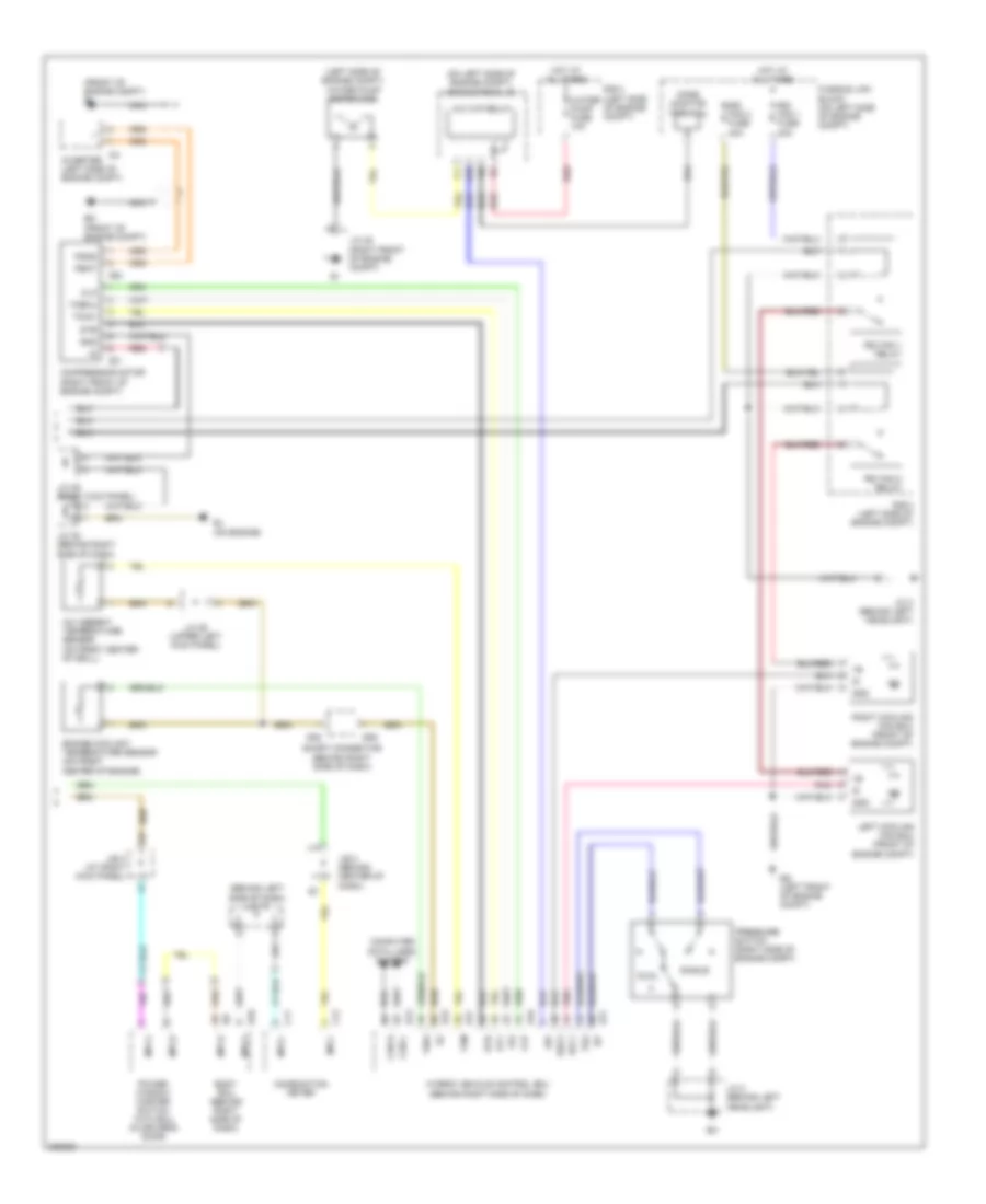
Horn Wiring Diagram for Toyota Celica GT 1991
List of elements for Horn Wiring Diagram for Toyota Celica GT 1991:
- (behind left side of dash) j/c 17
- (front of engine compt) el
- (left side of engine compt) water pump motor (a/c)
- (on left side of engine compt) engine room j/b
- A/c ambient temperature sensor (on front center of grill)
- A/c w/p relay
- B10
- Body ecu (behind right side of dash)
- C11
- C12
- C21
- C22
- Can h
- Can l
- Clk
- Combination meter
- Compressor motor (right front of engine compt)
- Computer data lines system
- Dual
- Eg (left front of engine compt)
- Ej (on engine)
- Em (front of engine compt)
- Engine coolant temperature sensor (on front center of engine)
- Et1
- Fusible link block (on left side of engine compt)
- Gnd
- H10
- H13
- H15
- H16
- H17
- Hot at all times
- Hybrid vehicle control ecu (behind right side of dash)
- I24
- Inverter (left side of engine compt)
- Ite
- J/b 3 (behind center of dash)
- J/b 4 (at right kick panel)
- J/c 2 (behind left headlight)
- J/c 25 (right front of engine compt)
- J/c 26 (upper left kick panel)
- J/c 35 (behind right side of dash)
- J/c 36 (right kick panel)
- J12
- Left cooling fan ecu (front of engine compt)
- Mode monitor terminal
- Mpx+
- Mpx-
- Mpx1
- Mpx2
- Nca
- Pbat
- Pgnd
- Pnk
- Power window master switch with ecu (in driver's door)
- Pr2
- Pressure switch (right side of engine compt)
- R/b 2 (left side of engine compt)
- R/b 3 (left side of engine compt)
- Rdi fan 1 fuse 40a
- Rdi fan 1 relay
- Rdi fan 2 fuse 40a
- Rdi fan 2 relay
- Rec2
- Red
- Rfc1
- Right cooling fan ecu (front of engine compt)
- S28
- S29
- Short connector (behind right side of dash)
- Single
- Stb
- Tam
- Thw
- Toecu
- Toinv
- Water pump fuse 10a
 English