POWER DOOR LOCKS
Power Door Lock Wiring Diagram for Toyota Celica GT 1991
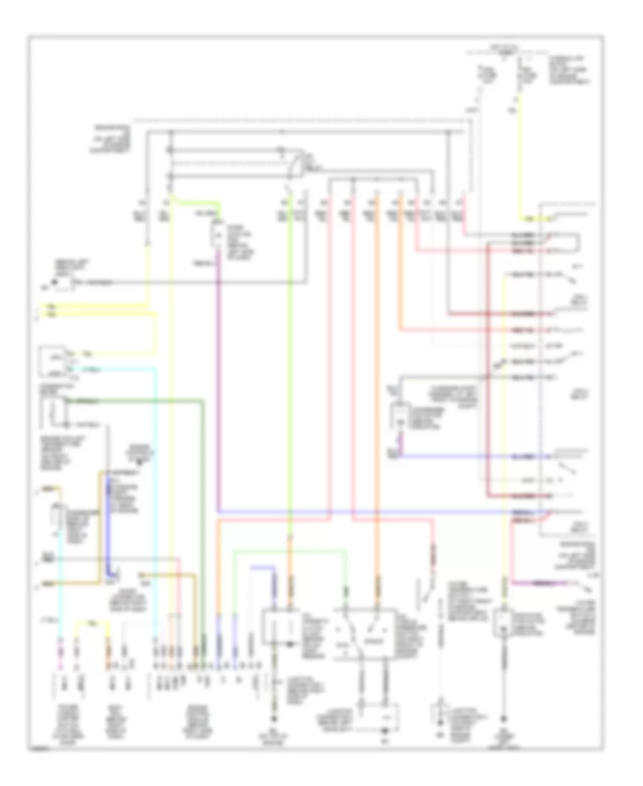
List of elements for Power Door Lock Wiring Diagram for Toyota Celica GT 1991:
- (behind left headlight) j/c 2
- (in engine compt harness, at left front of engine compt)
- A/c magnetic clutch & lock sensor (on a/c comp- ressor)
- A/c triple pressure switch (on right front of engine compt)
- Acmg
- B10
- Body ecu (behind right side of dash)
- C11
- C12
- Cds fuse 30a
- Combination meter
- Condenser fan motor (behind radiator)
- Diode (cooling fan) (behind left side of dash)
- Dual
- Ed (on top of engine)
- Eg (under left headlight)
- Engine control module (behind right side of dash)
- Engine controls system
- Engine coolant temperature sensor (on front center of engine)
- Engine room j/b (on left side of engine compartment)
- Engine room r/b (on left side of engine compartment)
- Fan 1 relay
- Fan 2 relay
- Fan 3 relay
- Fusible link block (on left side of engine compartment)
- Hot at all times
- Junction connector 2 (behind left headlight)
- Junction connector 4 (on right side of engine compt)
- Junction connector 7 (behind right side of dash)
- Lck1
- Mg clt relay
- Mpx+
- Mpx-
- Mpx1
- Mpx2
- Passenger side j/b (behind right side of dash)
- Power window master switch with ecu (in driver's door)
- Radiator fan motor (behind radiator)
- Rdi fuse 30a
- S28
- S29
- Short connector (behind right side of dash)
- Single
- Tam
- Thw
- Water temperature switch 1 (at right front of engine compartment, behind grille)
- Water temperature switch 2 (on rear center of engine)
 English