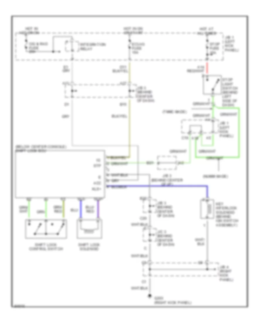
AUTOMOTIVE ELECTRICIANS PORTAL

SHIFT INTERLOCKS – Toyota Corolla CE 1997 – SYSTEM WIRING DIAGRAMS

SHIFT INTERLOCKS

Shift Interlock Wiring Diagram for Toyota Corolla CE 1997

Shift Interlock Wiring Diagram for Toyota Corolla CE 1997 https://portal-diagnostov.com/license.html
https://portal-diagnostov.com/license.html Automotive Electricians Portal FZCO Automotive Electricians Portal FZCO
Get access to all wiring diagrams of the carDownload PDF file

List of elements for Shift Interlock Wiring Diagram for Toyota Corolla CE 1997:

  • (below center console) shift lock ecu
  • (nummi made)
  • (tmmc made)
  • A11
  • A17
  • A18
  • Acc
  • B15
  • B20
  • B21
  • C10
  • C20
  • Cig & rad fuse 20a
  • Ecu-ig fuse 15a
  • G203 (right kick panel)
  • Hot at all times
  • Hot in acc or on
  • Hot in on or start
  • Integration relay
  • J/b 1 (left kick panel)
  • J/b 3 (behind center of dash)
  • J/b 3 (behind center of i/p)
  • J/b 4 (right kick panel)
  • J/c 3 (behind center of dash)
  • Key interlock solenoid (behind ign switch assembly)
  • Kls+
  • Shift lock control switch
  • Shift lock solenoid
  • Sls+
  • Sls-
  • Stop fuse 15a
  • Stop light switch (behind left side of dash)
  • Stp