TRANSMISSION
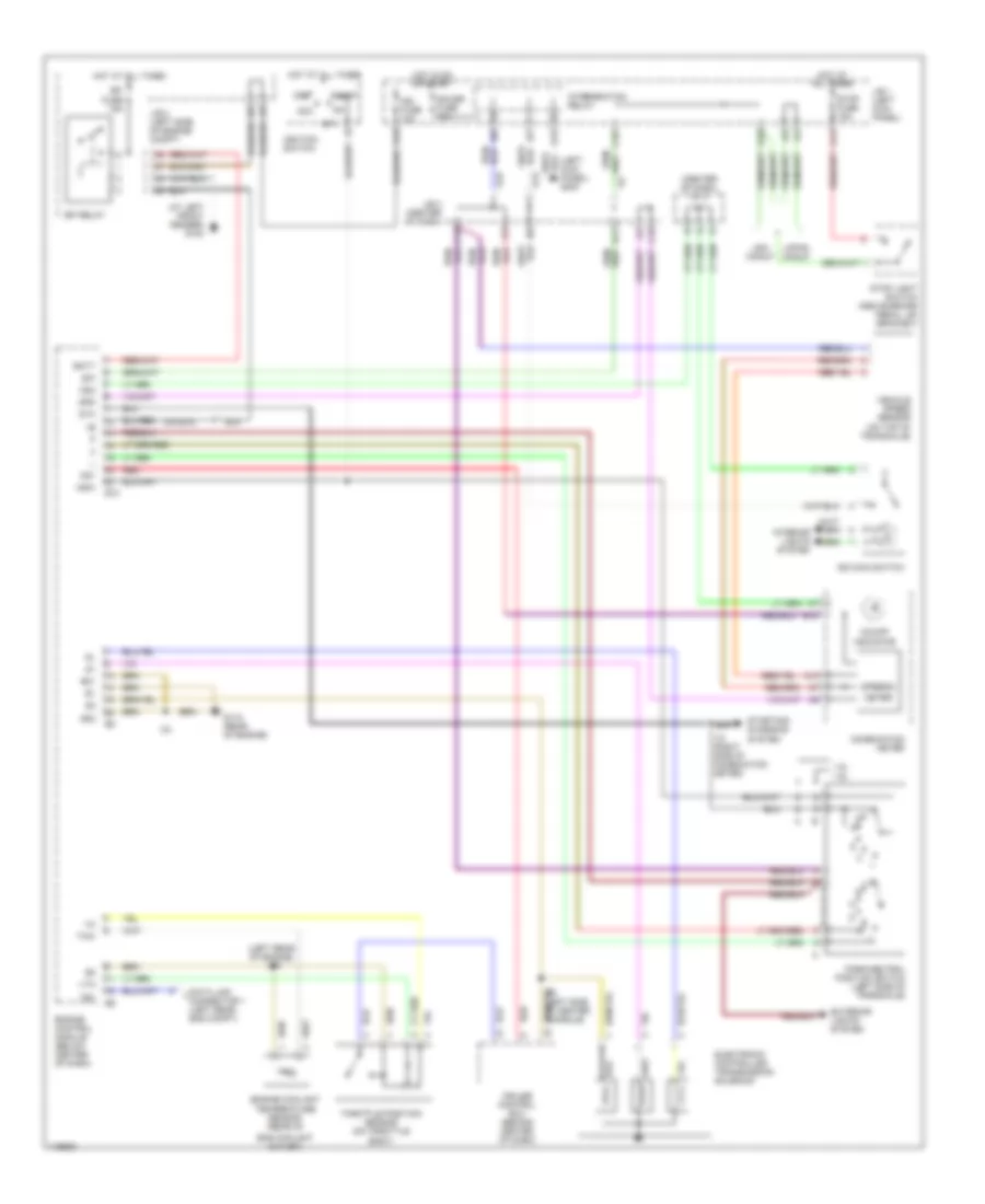
A/T Wiring Diagram for Toyota Corolla CE 1997
List of elements for A/T Wiring Diagram for Toyota Corolla CE 1997:
- (at left front fender) g100
- (center of dash) j/c 3
- (left kick panel) g200
- (left rear of engine)
- 1.8l 1.6l
- A10
- A13
- A14
- A15
- A18
- A19
- Acc
- B/k
- B12
- Batt
- C10
- C13
- C18
- Combination meter
- Cruise control ecu (behind center of dash)
- D11
- Data link
- E01
- E02
- E10
- E17
- Efi fuse 15a
- Efi relay
- Electronic controlled transmission solenoid
- Eng coolant outlet)
- Engine control module (below center of dash)
- Engine coolant
- Exterior lights system
- G115 (rear of engine)
- G15
- Gauge fuse 10a
- Hot at all times
- Hot in on or start
- I18 (right side of combination meter)
- I32 (left side of center console)
- I33
- Ign fuse 10a
- Ignition switch
- Indicator
- Intergration relay
- Interior lights system
- J/b 1 (left kick panel)
- J/b 2 (left side of engine compt)
- J/b 3 (center of dash)
- Japan manuf
- Meter
- Nsw
- O/d main switch
- O/d off
- Od1
- Od2
- Off
- Park/neutral position switch (left side of transaxle)
- Red
- Red/
- Spd
- Speedo-
- St1
- Sta
- Start
- Starting/ charging system
- Stop fuse 15a
- Stop light switch (above brake pedal, on bracket)
- T connector 1 (left rear eng compt)
- Te1
- Temperature sensor (rear of
- Throttle position sensor (on throttle body)
- Thw
- Usa manuf
- Vehicle speed sensor (on top of transaxle)
- Vta
 English