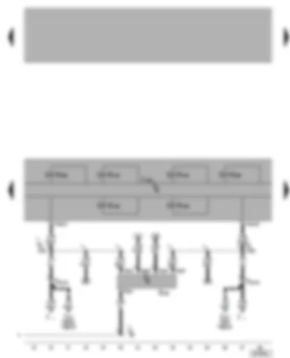
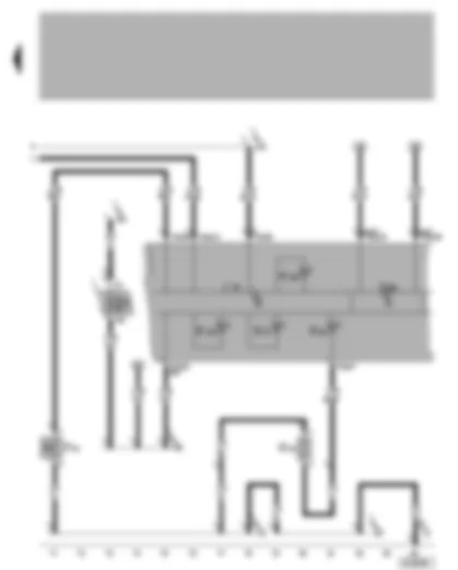
| A | Battery |
| D | Ignition/starter switch |
| E20 | Switches and instruments illumination regulator |
| E256 | TCS/ESP button |
| J104 | ABS with EDL/TCS/ESP control unit, on left in engine compartment |
| L71 | Traction control switch illumination |
| S9 | Fuse 9 in fuse holder |
| S178 | Fuse -6- (30), in fuse box/battery |
| S179 | Fuse -7- (30), in fuse box/battery |
| T3 | 3-pin connector |
| T6 | 6-pin connector |
| T6c | 6-pin connector |
| T47a | 47-pin connector |
| 42 | Earth point, next to steering column |
| 49 | Earth point, on steering column |
| 81 | Earth connection -1-, in dash panel wiring harness |
| 135 | Earth connection -2-, in dash panel wiring harness |
| A2 | Positive connection (15), in dash panel wiring harness |
| A4 | Positive (+) connection (58b), in dash panel wiring harness |
| A38 | Positive (+) connection -2- (15a), in dash panel wiring harness |
| A132 | Connection (TCS/ESP), in dash panel wiring harness |
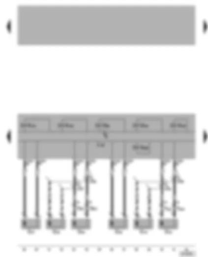
| G85 | Steering angle sender, on steering column |
| J104 | ABS with EDL/ TCS/ ESP control unit, in engine compartment, left |
| J217 | Automatic gearbox control unit |
| J... | Engine control units |
| N133 | ABS inlet valve, rear right |
| N134 | ABS inlet valve, rear left |
| N135 | ABS outlet valve, rear right |
| N136 | ABS outlet valve, rear left |
| N225 | Electronic stability program switch valve -1- |
| N226 | Electronic stability program switch valve -2- |
| T6a | 6-pin connector |
| T10w | 10-pin connector, white, in protective housing for connectors, in plenum chamber, left |
| T47a | 47-pin connector |
| T68 | 68-pin connector, only models with four speed automatic gearbox (AG4) |
| T68a | 68-pin connector, only models with five speed automatic gearbox (AG5) |
| 81 | Earth connection -1-, in dash panel wiring harness |
| A121 | Connection (high bus), in dash panel wiring harness |
| A122 | Connection (low bus), in dash panel wiring harness |
| --- | Only models with automatic gearbox control unit |
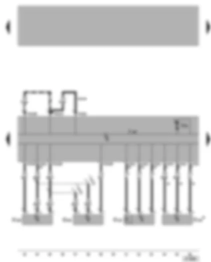
| G44 | Rear right speed sensor |
| G45 | Front right speed sensor |
| G46 | Rear left speed sensor |
| G47 | Front left speed sensor |
| J104 | ABS with EDL/ TCS/ ESP control unit, in engine compartment, left |
| N99 | ABS inlet valve, front right |
| N100 | ABS outlet valve, front right |
| N101 | ABS inlet valve, front left |
| N102 | ABS outlet valve, front left |
| N227 | Electronic stability program high pressure valve -1- |
| N228 | Electronic stability program high pressure valve -2- |
| T2a | 2-pin connector, near rear right speed sensor |
| T2b | 2-pin connector, near rear left speed sensor |
| T47a | 47-pin connector |
| D146 | Connection (rear left speed sensor +), in engine compartment wiring harness |
| D147 | Connection (rear left speed sensor -), in engine compartment wiring harness |
| D148 | Connection (rear right speed sensor +), in engine compartment wiring harness |
| D149 | Connection (rear right speed sensor -), in engine compartment wiring harness |
| * | Only models with four-wheel drive |
| -•-•- | Only models with four-wheel drive |
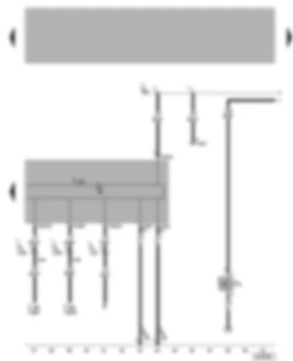
| G200 | Lateral acceleration sender, next to steering column |
| G201 | Brake pressure sender -1-, on brake master cylinder |
| G202 | Yaw rate sender, on steering column |
| G251 | Longitudinal acceleration sender, on right A-pillar* |
| J104 | ABS with EDL/ TCS/ ESP control unit, in engine compartment, left |
| T47a | 47-pin connector |
| V64 | ABS hydraulic pump |
| J3 | Connection -1-, in ABS wiring harness |
| J5 | Connection -2-, in ABS wiring harness |
| * | Only models with four-wheel drive |
| *** | Only models with ESP and four-wheel drive |
| -••- | Only models with ESP and front-wheel drive |
| F | Brake light switch |
| F9 | Handbrake warning switch |
| J104 | ABS with EDL/ TCS/ ESP control unit, in engine compartment, left |
| J503 | Control unit with display for radio and navigation** |
| T16 | 16-pin connector, in dash panel centre, self-diagnosis connection |
| T26 | 26-pin connector** |
| T47a | 47-pin connector |
| 65 | Earth point, longitudinal member left, front |
| A18 | Connection (54), in dash panel wiring harness |
| A76 | Connection (diagnosis wire K), in dash panel wiring harness |
| A133 | Connection (ABS impulse left), in dash panel wiring harness |
| A134 | Connection (ABS impulse right), in dash panel wiring harness |
| ** | Only models with navigation |
| F34 | Brake fluid level warning contact |
| G34 | Brake lining/pad wear sender, front left |
| J285 | Control unit with display in dash panel insert |
| J533 | Data bus diagnostic interface, in dash panel insert |
| K32 | Brake pad/lining warning lamp |
| K47 | ABS warning lamp |
| K118 | Brake system warning lamp |
| K155 | TCS/ESP warning lamp |
| S15 | Fuse in fuse box |
| T32 | 32-pin connector, blue |
| T32a | 32-pin connector, green |
| 12 | Earth point, in engine compartment, left |
| 119 | Earth connection -1-, in headlight wiring harness |
| 120 | Earth connection -2-, in headlight wiring harness |
| 501 | Screw connection -2- (30), on relay plate |
| A52 | Positive (+) connection (30a), in dash panel wiring harness |
| A76 | Connection (diagnosis wire K), in dash panel wiring harness |


 Deutsch
 English
 Español
 Français
 Nederlands
 Русский

