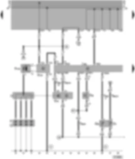
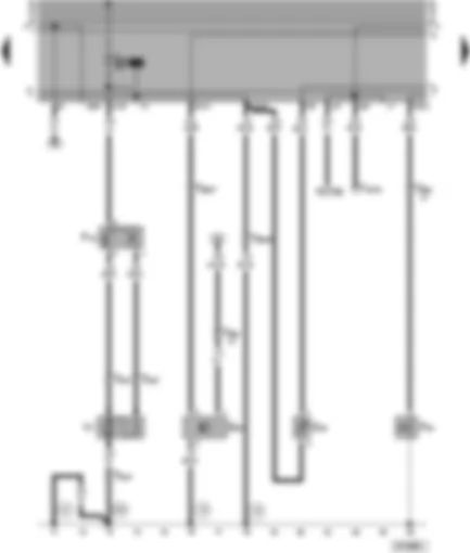
| F88 | Power assisted steering pressure switch |
| G2 | Coolant temperature sender |
| G40 | Hall sender |
| G62 | Coolant temperature sender |
| J362 | Immobilizer control unit, next to steering column |
| J382 | 1AV control unit (injection system), right in plenum chamber |
| N152 | Ignition transformer |
| N157 | Ignition transformer output stage |
| O | Ignition distributor |
| P | Spark plug connector |
| Q | Flame plug |
| T3 | 3-pin connector, on ignition transformer output stage |
| T6 | 6-pin connector, on immobilizer control unit |
| T28a | 28-pin connector, on engine |
| T45 | 45-pin connector, on 1AV control unit, (injection system) |
| 12 | Earth point, in engine compartment, left |
| 15 | Earth point, on cylinder head |
| 139 | Earth connection (sender earth), in Motronic wiring harness |
| E6 | Positive connection -1- (15), in Motronic wiring harness |
| E17 | Connection -2-, in Motronic wiring harness |
| * | For engine code AER only |
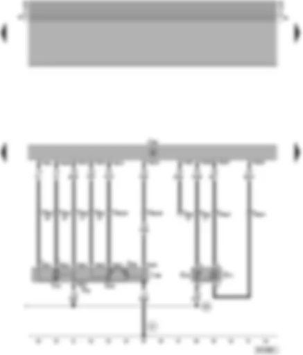
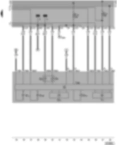
| F60 | Idling switch |
| G42 | Intake air temperature sender |
| G69 | Throttle valve potentiometer |
| G71 | Intake manifold pressure sender |
| G88 | Throttle valve positioner potentiometer |
| J338 | Throttle valve control unit |
| J382 | 1AV control unit (injection system), right in plenum chamber |
| T8h | 8-pin connector, on throttle valve control unit |
| T28a | 28-pin connector, on engine |
| T45 | 45-pin connector, on 1AV control unit, (injection system) |
| V60 | Throttle valve positioner |
| 15 | Earth point, on cylinder head |
| 139 | Earth connection (sender earth), in Motronic wiring harness |
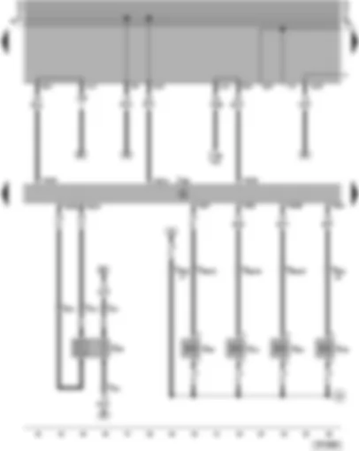
| G39 | Lambda probe |
| J362 | Immobilizer control unit, next to steering column |
| J382 | 1AV control unit (injection system), right in plenum chamber |
| N30 | Injector, cylinder 1 |
| N31 | Injector, cylinder 2 |
| N32 | Injector, cylinder 3 |
| N33 | Injector, cylinder 4 |
| T4 | 4-pin connector, on gearbox |
| T6 | 6-pin connector, on immobilizer control unit |
| T28a | 28-pin connector, on engine |
| T45 | 45-pin connector, on 1AV control unit, (injection system) |
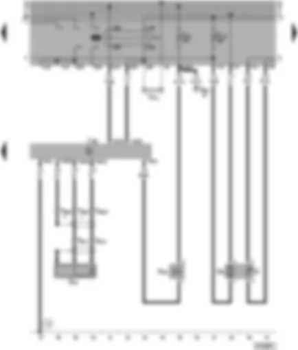
| G3 | Positive (+) connection in cable sleeve - injectors |
| G | Fuel gauge sender |
| G6 | Fuel pump (pre-supply pump) |
| G61 | Knock sensor I |
| J17 | Fuel pump relay (01259) |
| J382 | 1AV control unit (injection system), right in plenum chamber |
| N80 | Activated charcoal filter system solenoid valve I |
| T2c | 2-pin connector, on engine |
| T28a | 28-pin connector, on engine |
| T45 | 45-pin connector, on 1AV control unit, (injection system) |
| TV2 | Terminal 30 junction box, behind the relay plate |
| 12 | Earth point, in engine compartment, left |
| F18 | Radiator fan thermo-switch |
| F22 | Oil pressure switch (0.3 bar) |
| G22 | Speedometer sender (Hall sender on gearbox) |
| G32 | Coolant shortage indicator sender |
| T3a | 3-pin connector, on radiator fan |
| T16 | 16-pin connector, behind shelf on driver's side, self-diagnosis socket for V.A.G 1551 |
| T28a | 28-pin connector, on engine |
| V7 | Radiator fan |
| W | Interior light, front |
| W3 | Luggage compartment light |
| 12 | Earth point, in engine compartment, left |
| 15 | Earth point, on cylinder head |
| 210 | Earth connection -1-, in Motronic wiring harness |


 Deutsch
 English
 Español
 Français
 Nederlands
 Русский

