ENGINE ACCESSORIES
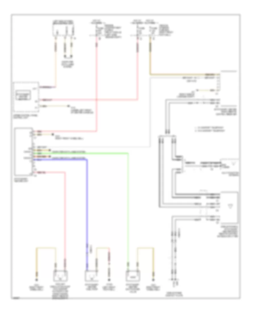
Stationary Heater Wiring Diagram for Mercedes-Benz CLA250 2014
List of elements for Stationary Heater Wiring Diagram for Mercedes-Benz CLA250 2014:
- (+)
- (left end of dash) sam control unit
- (left front footwell)
- A tel
- Can b h
- Can b l
- Computer data lines system
- Coolant circulation pump (w/o comfort automatic air conditioning) (right rear of engine compt)
- Engine compartment fuse & relay module (left side engine compt)
- Fuse 20a
- Fuse 5a
- Hot at all times
- Lin 1
- Mobile phone & stationary heater radio remote control antenna splitter
- Mobile phone contact plate
- Multi-function antenna
- Nca
- Red
- Shd
- Shd a sdar
- Sig
- Stationary heater button
- Stationary heater fuel pump
- Stationary heater radio remote control receiver
- Stationary heater switchover valve
- Stationary heater unit
- Upper control panel control unit
- Vehicle interior fuse box (right front footwell)
- W/ comfort telephony
- W/o comfort telephony
- W12 (under left front of center console)
- W15/2
- W3/1 (right front wheelwell)
- W7 (right side of luggage compt)
- X25/14-c2
- X36/2-c1
- X39/37-c1
 English