ENGINE PERFORMANCE
5.4L
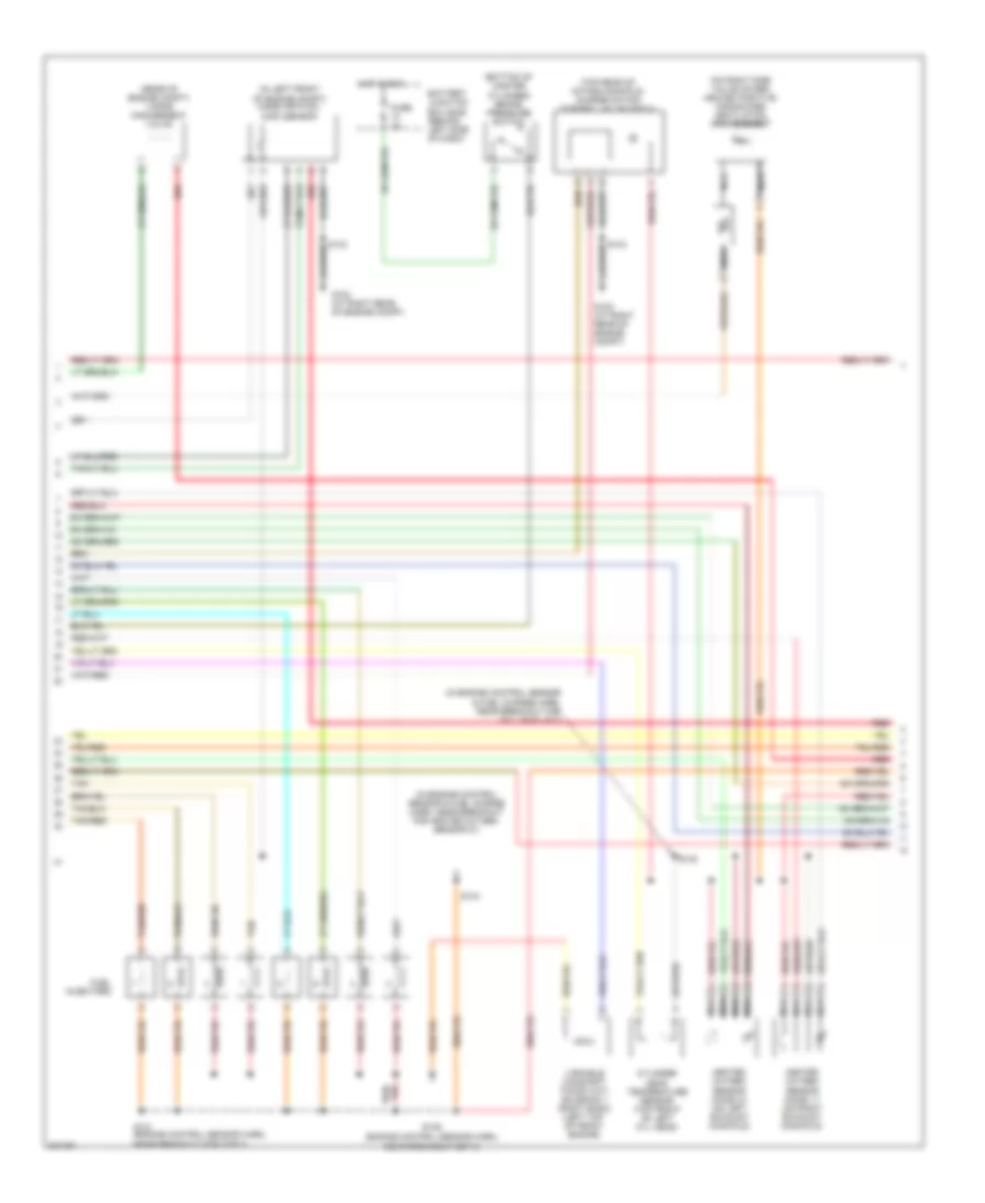
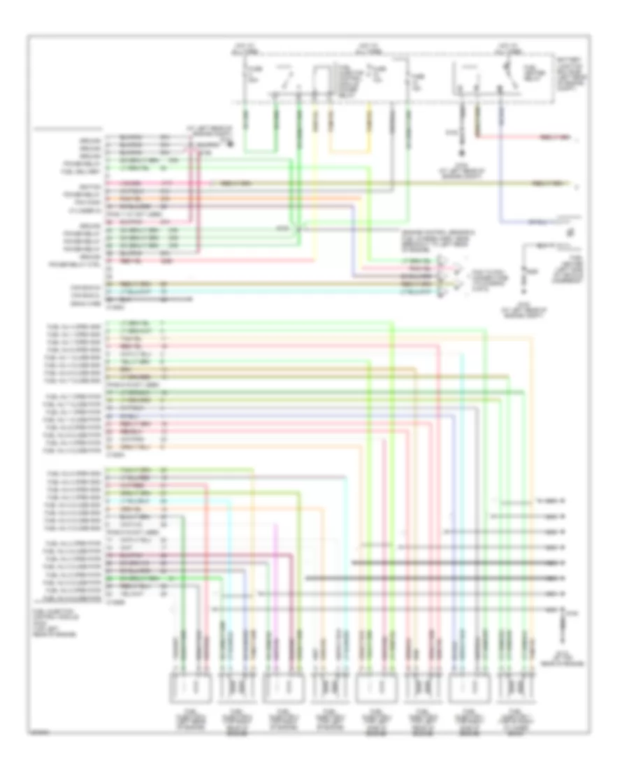
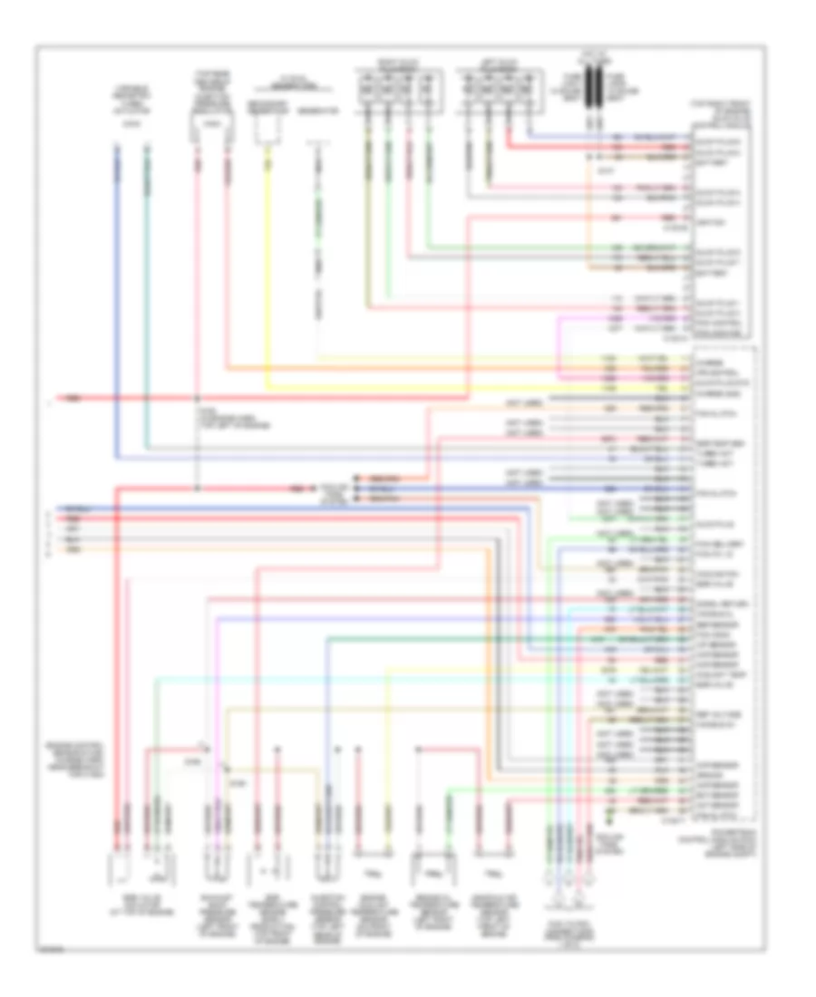
5.4L, Engine Performance Wiring Diagram (1 of 5) for Ford Cab & Chassis F350 Super Duty 2005

List of elements for 5.4L, Engine Performance Wiring Diagram (1 of 5) for Ford Cab & Chassis F350 Super Duty 2005:
- (in engine control sensor & fuel charge harn, near breakout for c175a)
- A/c clutch rly
- A/c press sw
- A/c system
- Brake pressure sw
- C175a
- Camshaft position sensor (left bank) (on lower front center of engine)
- Camshaft position sensor (right bank) (on lower right front of engine)
- Ckp sensor +
- Ckp sensor -
- Cmcv cntrl
- Cmcv monitor
- Cmp sensor 1
- Cmp sensor 2
- Coil on plug
- Coil on plug 1
- Coil on plug 2
- Coil on plug 3
- Coil on plug 4
- Coil on plug 5
- Coil on plug 6
- Coil on plug 7
- Coil on plug 8
- Crankshaft position sensor (on front of left cylinder head)
- Cyl head temp
- Engine oil temperature sensor (eot) (lower right rear of engine block)
- Eot sensor
- Etc motor
- Fuel inj 1
- Fuel inj 2
- Fuel inj 3
- Fuel inj 4
- Fuel inj 5
- Fuel inj 6
- Fuel inj 7
- Fuel inj 8
- Fuel rail press sen
- Fuel rail temp sens
- Ho2s 11 htr
- Ho2s 11 input
- Ho2s 21 htr
- Ho2s 21 input
- Iat sensor
- Ignition transformer capacitor 1 (right front of engine)
- Ignition transformer capacitor 2 (on rear of right cylinder head)
- Injection pressure sensor (ips) (top left center of intake manifold)
- Knock sensor 1 +
- Knock sensor 1 -
- Knock sensor 2 +
- Knock sensor 2 -
- Maf sensor
- Nca
- Pcv valve
- Powertrain control module (on left side of firewall)
- Reference voltage
- S130 (in engine control sensor & fuel charge harn, near breakout for fuel inj 6)
- S135 (in engine control sensor & fuel charge harn, near breakout for fuel inj 3)
- S145
- Shield drain
- Signal return
- Tan
- Tan/red
- Throttle position sensor (top of engine, near air intake)
- Tps 1 sig
- Tps 2 sig
- Tps ref
- Tps sig return
- Vapor man valve
- Vct sol 1
- Vct sol 2
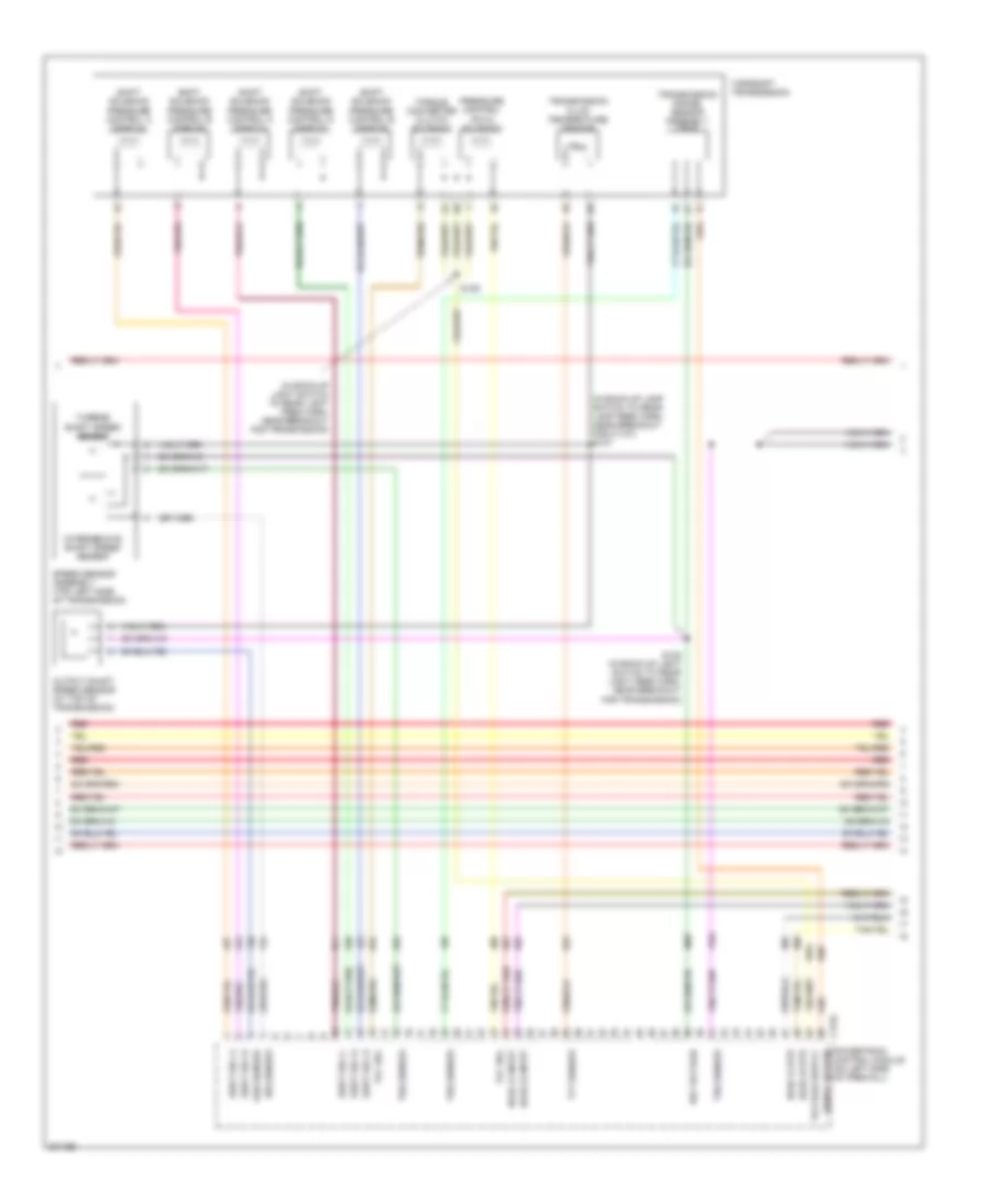
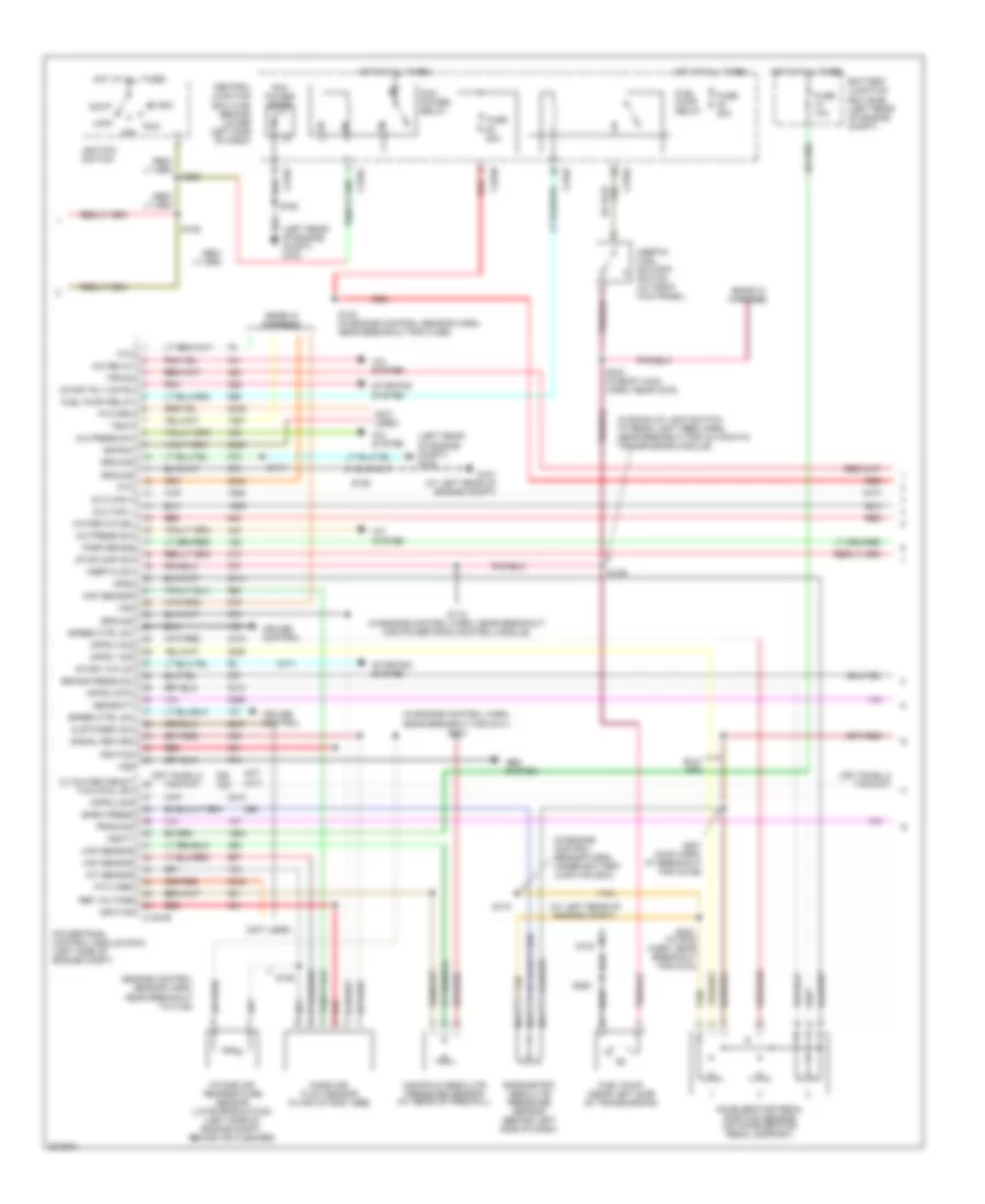
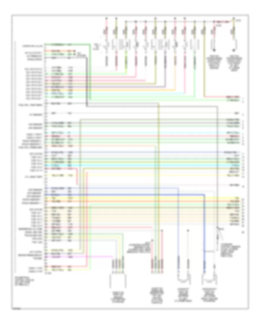
5.4L, Engine Performance Wiring Diagram (2 of 5) for Ford Cab & Chassis F350 Super Duty 2005
List of elements for 5.4L, Engine Performance Wiring Diagram (2 of 5) for Ford Cab & Chassis F350 Super Duty 2005:
- (bottom of master cylinder) brake pressure switch
- (engine control sensor harn, near breakout cop 3)
- (engine control sensor harn, near breakout for cop 7)
- (in engine control sensor & fuel charge harn, near breakout for coil on plug 7)
- (in engine control sensor & fuel charge harn, near breakout for heated oxygen sensor 21)
- (in left front of engine compt) mass air flow (maf) sensor
- (on right side valve cover) heated positive crankcase ventilation (pcv) element
- (rear of engine compt) vapor management valve
- (top rear of intake manifold) charge motion control valve (cmcv)
- Battery junction box (bjb) (behind left side of dash)
- Cylinder head temperature sensor (top front of left cyl head)
- Fuel injectors
- Fuse 2a
- G102 (at right rear of engine compt)
- Heated oxygen sensor (ho2s) 11 (on right exhaust manifold)
- Heated oxygen sensor (ho2s) 21 (on left exhaust manifold)
- Hot in run
- Nca
- Red
- S131
- S132
- S134
- S136
- Tan
- Tan/red
- Variable camshaft timing (vct) solenoid 1 (right bank) (left top of front engine)
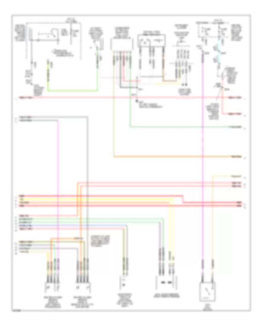
5.4L, Engine Performance Wiring Diagram (3 of 5) for Ford Cab & Chassis F350 Super Duty 2005
List of elements for 5.4L, Engine Performance Wiring Diagram (3 of 5) for Ford Cab & Chassis F350 Super Duty 2005:
- (in back-up lamp switch to rear lamp feed harn, near breakout for c1107) s127
- (in back-up light switch to rear light feed harn, near breakout for transmission)
- C175c
- Ho2s 12 htr
- Ho2s 12 input
- Ho2s 22 htr
- Ho2s 22 input
- Intermediate shaft speed sensor
- Iss sensor
- Oss sensor
- Output shaft speed sensor (at top of transmission)
- Powertrain control module (on left side of firewall)
- Pressure control (pc-a) solenoid
- Red
- Ref voltage
- S128 (in back-up light switch to rear light feed harn, near breakout for transmission)
- S129
- Shift sol a
- Shift sol b
- Shift sol c
- Shift sol d
- Shift sol e
- Shift solenoid pressure control a (sspc-a)
- Shift solenoid pressure control b (sspc-b)
- Shift solenoid pressure control c (sspc-c)
- Shift solenoid pressure control d (sspc-d)
- Shift solenoid pressure control e (sspc-e)
- Signal return
- Speed sensor assembly (top left side of transmission)
- Tcc sol
- Tft sensor
- Torqshift transmission
- Torque converter clutch solenoid
- Transmission fluid temperature sensor
- Transmission range sensor assembly (tr-p)
- Trs sensor
- Tss sensor
- Turbine shaft speed sensor
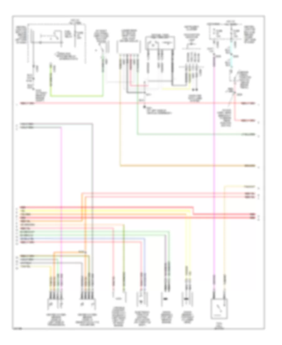
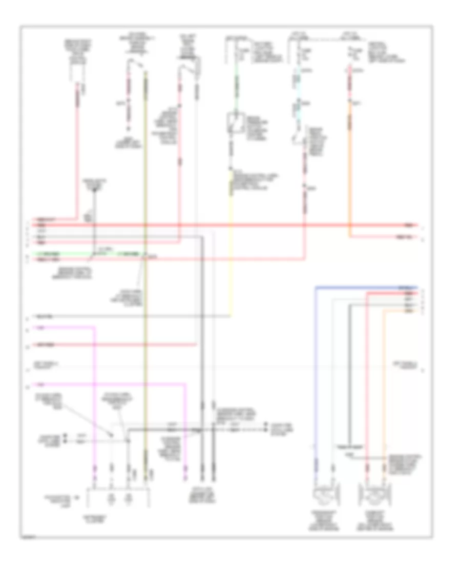
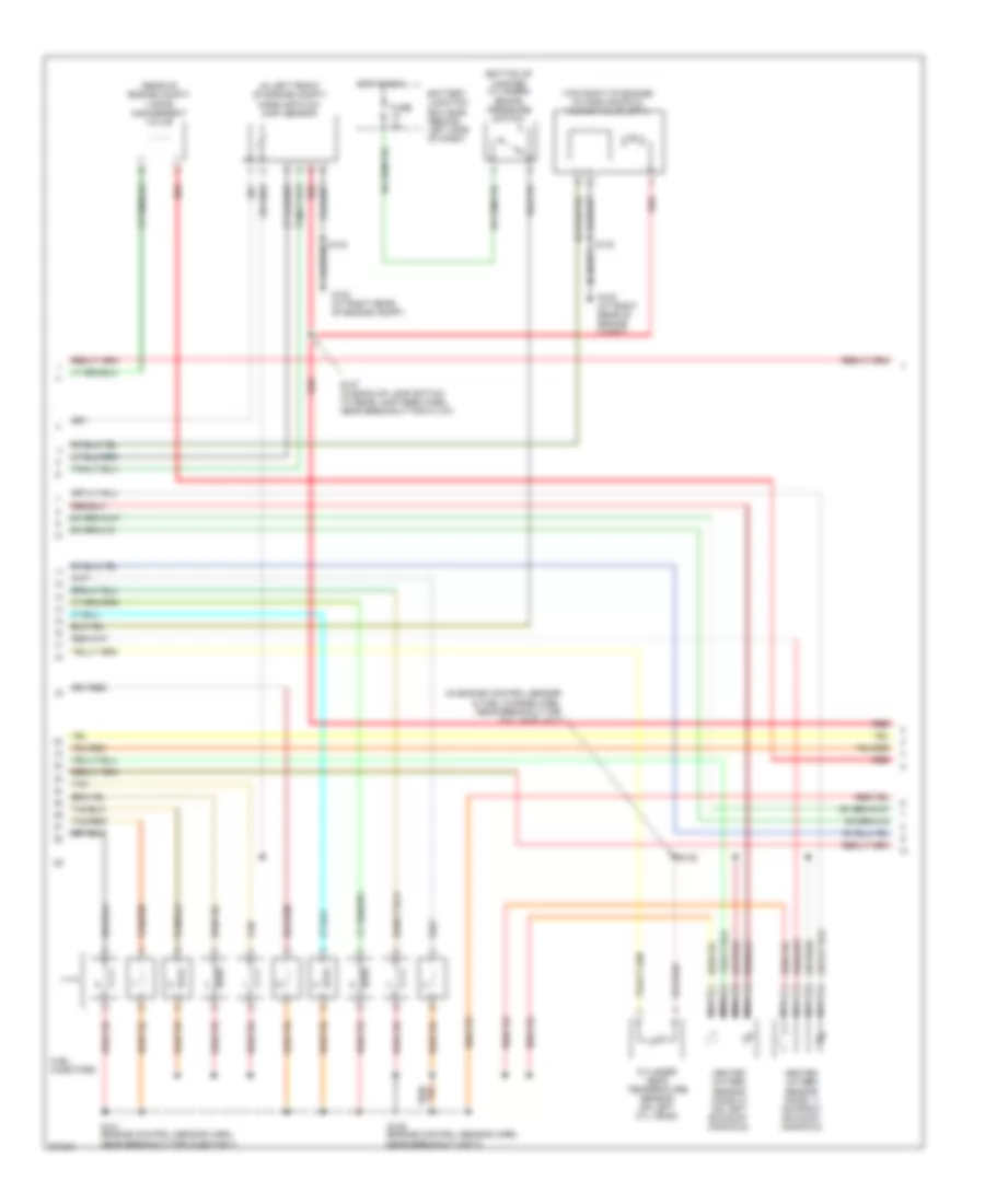
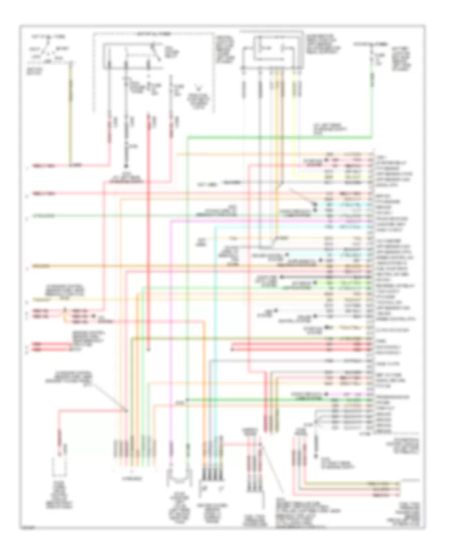
5.4L, Engine Performance Wiring Diagram (4 of 5) for Ford Cab & Chassis F350 Super Duty 2005
List of elements for 5.4L, Engine Performance Wiring Diagram (4 of 5) for Ford Cab & Chassis F350 Super Duty 2005:
- (at right kick panel) inertia fuel shut-off switch
- (in main harn, near breakout to brake pedal position switch)
- (on fuel tank) fuel tank unit
- (under rear of vehicle, near tank) fuel pump driver module
- Brake pedal position switch (above brake pedal)
- C270a
- C270f
- Central junction box (cjb) (behind lower left side of dash)
- Computer data lines system
- Electronic throttle control (etc) motor (on throttle body)
- From pcm power relay (diagram 5 of 5)
- Fuel lvl
- Fuel pump relay
- Fuse 10a
- Fuse 15a
- Fuse 20a
- G102 (at right rear of engine compt)
- G401 (at left side of vehicle underbody)
- Heated oxygen sensor (ho2s) 12 (rear of catalytic converter)
- Heated oxygen sensor (ho2s) 22 (left side of transmission)
- Hot at all times
- Hot in run
- Hs can +
- Hs can -
- Instrument cluster
- Knock sensor 1 (top right cylinder head)
- Knock sensor 2 (top left rear of engine)
- Malfunction indicator lamp
- Nca
- Red
- Return
- S106
- S138
- S205
- S208
- S235
- S411
- Tow/ haul switch
- Variable camshaft timing (vct) solenoid 2 (left bank) (left top of front engine)
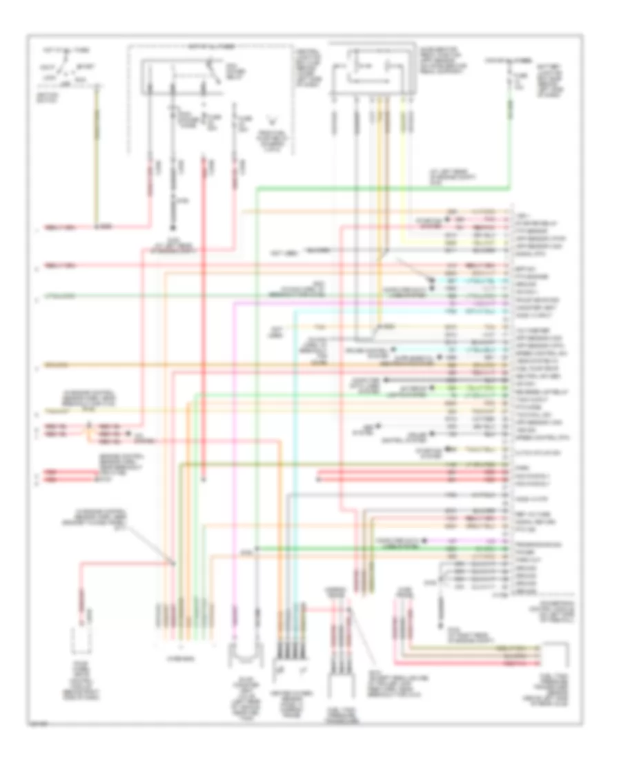
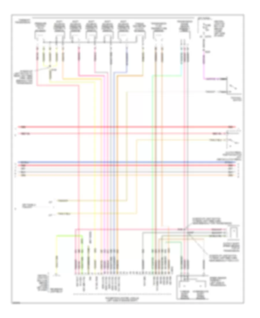
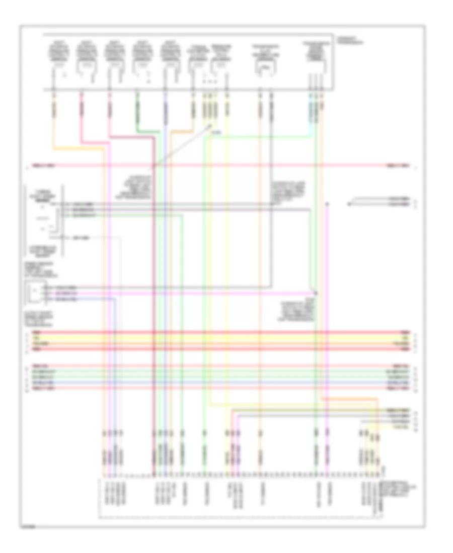
5.4L, Engine Performance Wiring Diagram (5 of 5) for Ford Cab & Chassis F350 Super Duty 2005
List of elements for 5.4L, Engine Performance Wiring Diagram (5 of 5) for Ford Cab & Chassis F350 Super Duty 2005:
- (at left rear of engine compt) g100
- (engine control sensor harn, near breakout for c1756) s123
- (in engine control sensor harn, near breakout for c140) s122
- (in engine control sensor harn, near grommet in dash panel) s111
- (in main harn, at breakout for c2186)
- (not used)
- (wire end)
- A/c system
- Abs system
- Acc
- Accelerator pedal position (app) sensor (on accelerator pedal support)
- App sensor 2 sig
- App sensor 3 pwr
- App sensor 3 rtn
- App sensor 3 sig
- Battery junction box (bjb) (behind left side of dash)
- Bpp sw
- C175b
- C270c
- C270f
- C270h
- C281b
- Canister vent
- Central junction box (cjb) (behind lower left side of dash)
- Cltch intlck sw
- Computer data lines system
- Cruise control system
- Evap canister vent valve (left rear of vehicle, near fuel tank)
- Exterior lights system
- Four- wheel drive control module (behind right side of dash)
- Fpump drvr mod
- From fuel pump relay (diagram 4 of 5)
- Ftp sensor
- Fuel pump drvr
- Fuel tank pressure transducer
- Fuel tank pressure transducer sensor (above left side of rear axle)
- Fuse 10a
- Fuse 20a
- G100 (at left rear of engine compt)
- G102 (at right rear of engine compt)
- Ground
- Heated oxygen sensor (ho2s) 13 (narrow frame)
- Ho2s 13 htr
- Ho2s 13 input
- Hot at all times
- Hs can +
- Hs can -
- Ignition switch
- Lock
- Narrow frame
- Nca
- Neutral sw sen
- Off
- Park
- Park out
- Pcm power diode
- Pcm power relay
- Pcm pwr rly
- Pnk
- Power
- Powertrain control module (on left side of firewall)
- Programming sig
- Pto engage
- Pto ind
- Pto mode
- Red
- Red/pnk
- Ref voltage
- Reverse lmp relay
- Run
- S106
- S162
- S164
- S221 (in main harn, at breakout for c2186)
- S223
- S258
- S412 (except regular cab) (in trailer lamp feed harn, near breakout for c410)
- Signal return
- Signal rtn
- Speed control rtn
- Speed control sw
- Start
- Starter relay
- Starting system
- Tach ouput
- Tan
- Tow/haul sw
- Vems system in
- Voltage ref
- Vss +
- Vss sig
- Wide frame
6.0L DIESEL
6.0L Diesel, Engine Performance Wiring Diagram (1 of 5) for Ford Cab & Chassis F350 Super Duty 2005
List of elements for 6.0L Diesel, Engine Performance Wiring Diagram (1 of 5) for Ford Cab & Chassis F350 Super Duty 2005:
- (at left rear of engine compt) g101
- (engine control sensor & fuel charge harn, near breakout to left rear of engine)
- (pins 11-21 not used)
- (pins 9-16 not used)
- Battery junction box (bjb) (left rear of engine compt)
- C1388a
- C1388b
- C1388c
- Can bus 2h
- Can bus 2l
- Cylinder id
- Drain wire
- Ficm to pcm connections (to diagram 5 of 5)
- Fuel delivery
- Fuel heater (left side of vehicle underbody
- Fuel heater relay
- Fuel inj 1 close gnd
- Fuel inj 1 close pwr
- Fuel inj 1 open gnd
- Fuel inj 1 open pwr
- Fuel inj 2 close gnd
- Fuel inj 2 close pwr
- Fuel inj 2 open gnd
- Fuel inj 2 open pwr
- Fuel inj 3 close gnd
- Fuel inj 3 close pwr
- Fuel inj 3 open gnd
- Fuel inj 3 open pwr
- Fuel inj 4 close gnd
- Fuel inj 4 close pwr
- Fuel inj 4 open gnd
- Fuel inj 4 open pwr
- Fuel inj 5 close gnd
- Fuel inj 5 close pwr
- Fuel inj 5 open gnd
- Fuel inj 5 open pwr
- Fuel inj 6 close gnd
- Fuel inj 6 close pwr
- Fuel inj 6 open gnd
- Fuel inj 6 open pwr
- Fuel inj 7 close gnd
- Fuel inj 7 close pwr
- Fuel inj 7 open gnd
- Fuel inj 7 open pwr
- Fuel inj 8 close gnd
- Fuel inj 8 close pwr
- Fuel inj 8 open gnd
- Fuel inj 8 open pwr
- Fuel injection control module (ficm) (top left rear of engine)
- Fuel injector 1 (top right side of engine)
- Fuel injector 2 (top left of engine)
- Fuel injector 3 (top right of engine)
- Fuel injector 4 (top left side of engine)
- Fuel injector 5 (top right rear of engine)
- Fuel injector 6 (top left rear of engine)
- Fuel injector 7 (top of right cylinder bank)
- Fuel injector 8 (left rear of engine)
- Fuel injector control module power relay
- Fuse 10a
- Fuse 15a
- Fuse 50a
- G100 (at left rear of engine compt)
- G110 (at top rear of engine)
- Ground
- Hot at all times
- Ignition
- Nca
- Pcm comm
- Power relay
- Power relay ctrl
- S102
- S120
- S194
- S195
- S250
6.0L Diesel, Engine Performance Wiring Diagram (2 of 5) for Ford Cab & Chassis F350 Super Duty 2005
List of elements for 6.0L Diesel, Engine Performance Wiring Diagram (2 of 5) for Ford Cab & Chassis F350 Super Duty 2005:
- (at left rear of engine compt)
- (ends in harness)
- (engine control sensor harn, near breakout to c128)
- (in back-up light switch to rear light feed harn, near breakout for automatic transmission module)
- (in engine control harn, near breakout for g101) s114
- (in engine control sensor harn, under battery junction box)
- (in main harn, near breakout for c218)
- (left rear of engine compt) g100
- (m/t)
- (m/t) (a/t)
- (not used)
- A/c press sw
- A/c relay
- A/c system
- Abs system
- Acc
- Accelerator pedal position sensor (on accelerator pedal support)
- Apps 1 sig
- Apps 2 rtn
- Apps 2 sig
- Apps 3 sig
- Aps2
- Baro press
- Barometric absolute pressure sensor (behind left side of dash)
- Battery junction box (bjb) (left rear of engine compt)
- Bcpsw
- Brake press sw
- C1381b
- C270a
- C270c
- C270f
- C270h
- Central junction box (cjb) (behind lower left side of dash)
- Cltch ped deact
- Cruise control
- Cto
- Customer acc
- Dlc can h
- Dlc can l
- Fuel pump (near left side of transmission)
- Fuel pump relay
- Fuse 10a
- Fuse 20a
- G100
- G101 (at left rear of engine compt)
- Gen/batt
- Ground
- Hot at all times
- Iat sensor
- Ignition
- Ignition switch
- Inertia fuel shutoff switch (at right kick panel)
- Inertia sw
- Intake air temperature sensor (late production) (left side of engine compt, behind air cleaner)
- Lock
- Maf sensor
- Manifold absolute pressure sensor (at rear of firewall)
- Map sensor
- Mass air- flow sensor (in air intake tube)
- Nca
- Off
- Park brake
- Pcm power diode
- Pcm power relay
- Pnk
- Powertrain control module (pcm) (left side of engine compt)
- Prog sig
- Pto
- Pto rpm
- Pto vref
- Red
- Ref voltage
- Run
- S106
- S117
- S118 (in engine control harn, near breakout for powertrain control module)
- S123 (in engine control sensor harn, near breakout for c1298)
- S139
- S150
- S162
- S170
- S182
- S221 (main harn, at breakout for c2186)
- S223
- S234 (in body main harn, near c278)
- S250
- S258
- Signal return
- Speed ctrl sw
- Start
- Start intlck
- Start rly cntrl
- Starting system
- Stoplamp sw
- Tan
- Tow/haul sw
- Tr0-n2
- Tr0-p
- Vbatt
- Vso
- Vss
- Water in fuel
6.0L Diesel, Engine Performance Wiring Diagram (3 of 5) for Ford Cab & Chassis F350 Super Duty 2005
List of elements for 6.0L Diesel, Engine Performance Wiring Diagram (3 of 5) for Ford Cab & Chassis F350 Super Duty 2005:
- (behind right side of dash) four wheel drive control module
- (engine control sensor & fuel charge harn, at breakout for c1381c)
- (engine control sensor harn, at breakout for g100)
- (in engine control sensor harn, near breakout to c135)
- (in main harn, at breakout for (dlc)) s220
- (in main harn, near breakout for (dlc)) s213
- (main harn, at breakout for instrument cluster)
- (on left frame rail) water- in-fuel sensor
- (on park brake assembly) parking brake switch
- (w/ drl)
- Battery junction box (bjb) (left rear of engine compt)
- Brake pedal position switch (above brake pedal)
- Brake pressure switch (on brake master cylinder)
- C220a
- C220b
- C270a
- C281b
- Camshaft position sensor (on lower front center of engine)
- Central junction box (cjb) (behind lower left side of dash)
- Computer data lines system
- Crankshaft position sensor (lower right side of engine)
- Data link connector (behind left side of dash)
- Fuse 10a
- Fuse 2a
- G300 (under left side of dash)
- Headlights system (w/ drl)
- Hot at all times
- Hot in run
- Hs can (+)
- Hs can (-)
- Instrument cluster
- Malfunction indicator lamp
- Nca
- Red
- S110 (engine control harn, near breakout for powertrain control module)
- S112 (engine control harn, near breakout for powertrain control module)
- S142
- S174
- S197
- S205
- S208
- S271
- S278
- Sensor harn, near breakout to g300) s140
6.0L Diesel, Engine Performance Wiring Diagram (4 of 5) for Ford Cab & Chassis F350 Super Duty 2005
List of elements for 6.0L Diesel, Engine Performance Wiring Diagram (4 of 5) for Ford Cab & Chassis F350 Super Duty 2005:
- (a/t)
- (in back-up lamp switch to rear lamp feed harn, near breakout for c1107)
- (in back-up light switch to rear light feed harn, near breakout for transmission)
- (not used)
- A/t
- C1381e
- C270a
- Central junction box (cjb) (behind lower left side of dash)
- Clutch pedal position switch (m/t) (above clutch pedal)
- Fuse 15a
- Hot in run
- Intermediate shaft speed sensor
- Iss sig
- M/t
- Nca
- Oss sig
- Output shaft speed sensor (top of transmission)
- Pc sol pwr
- Pc-a sol
- Powertrain control module (left side of engine compt)
- Pressure control (pc-a) solenoid
- Red
- Ref volt
- Rev lmp ctrl
- Reversing lamp relay
- S127
- S128
- S129
- S235
- Shift solenoid pressure control a (sspc-a)
- Shift solenoid pressure control b (sspc-b)
- Shift solenoid pressure control c (sspc-c)
- Shift solenoid pressure control d (sspc-d)
- Shift solenoid pressure control e (sspc-e)
- Sig trn
- Speed sensor assembly (left side of transmission)
- Sspc-a crl
- Sspc-b ctrl
- Sspc-c crl
- Sspc-d ctrl
- Sspc-e ctrl
- Tcc sol ctrl
- Tft sens sig
- Torqshift transmission
- Torque converter clutch solenoid
- Tow/haul switch
- Tr-p gnd
- Tr-p sig
- Transmission fluid temperature sensor
- Transmission range sensor assembly (tr-p)
- Tro
- Tss sig
- Turbine shaft speed sensor
6.0L Diesel, Engine Performance Wiring Diagram (5 of 5) for Ford Cab & Chassis F350 Super Duty 2005
List of elements for 6.0L Diesel, Engine Performance Wiring Diagram (5 of 5) for Ford Cab & Chassis F350 Super Duty 2005:
- (engine control sensor & fuel charge harn, near breakout for c1064)
- (not used)
- (top rear center of engine) injection pressure regulator
- (top right front of engine) glow plug control module
- Act sensor
- Battery
- C1301a
- C1301b
- C1381t
- Can bus 2h
- Can bus 2l
- Charge
- Charge (2nd)
- Ckp sensor
- Cmp sensor
- Coolant temp
- Cooling fan
- Cooling fans system
- Ebp sensor
- Egr temp sen
- Egr temperature sensor (early production) (top front of engine)
- Egr valve
- Egr valve actuator (at top of engine)
- Engine coolant temperature sensor (on front of engine)
- Engine oil temperature sensor (left right of engine)
- Eot sensor
- Exhaust back pressure sensor (left front of engine)
- Fan clutch
- Ficm comm
- Ficm cyl id
- Ficm delivery
- Ficm to pcm connections (from diagram 1 of 5)
- Fuse link f 12 gauge gray
- Fuse linkg 12 gauge gray
- Generator
- Glow plug
- Glow plug 1
- Glow plug 2
- Glow plug 3
- Glow plug 4
- Glow plug 5
- Glow plug 6
- Glow plug 7
- Glow plug 8
- Glow plug sys
- Ground
- Hot at all times
- Icp sensor
- Ignition
- Injection control pressure sensor (top left rear of engine)
- Ipr control
- Left glow plug bank
- Manifold air temperature sensor (top left front of engine)
- Nca
- Pcm control
- Pcm monitor
- Powertrain control module (pcm) (left side of engine compt)
- Red
- Ref voltage
- Right glow plug bank
- S147
- S190
- S192
- S193 (in engine harn, top left of engine)
- Secondary generator
- Signal return
- Turbo act
- Variable geometric turbo actuator
- W/ dual generators
6.8L
6.8L, Engine Performance Wiring Diagram (1 of 5) for Ford Cab & Chassis F350 Super Duty 2005
List of elements for 6.8L, Engine Performance Wiring Diagram (1 of 5) for Ford Cab & Chassis F350 Super Duty 2005:
- (in engine control sensor & fuel charge harn, near breakout for c175a)
- A/c clutch rly
- A/c press sw
- A/c system
- Brake pressure sw
- C175a
- Camshaft position sensor (on front of left cylinder head)
- Ckp sensor +
- Ckp sensor -
- Cmp sensor
- Coil on plug
- Coil on plug 1
- Coil on plug 10
- Coil on plug 2
- Coil on plug 3
- Coil on plug 4
- Coil on plug 5
- Coil on plug 6
- Coil on plug 7
- Coil on plug 8
- Coil on plug 9
- Crankshaft position sensor (on lower front center of engine)
- Cyl head temp
- Etc motor
- Fuel inj 1
- Fuel inj 10
- Fuel inj 2
- Fuel inj 3
- Fuel inj 4
- Fuel inj 5
- Fuel inj 6
- Fuel inj 7
- Fuel inj 8
- Fuel inj 9
- Fuel rail press sen
- Fuel rail temp sens
- Ho2s 11 htr
- Ho2s 11 input
- Ho2s 21 htr
- Ho2s 21 input
- Iat sensor
- Ignition transformer capacitor 1 (top right front of engine)
- Ignition transformer capacitor 2 (top front of left cylinder head)
- Imtv cntrl
- Injection pressure sensor (ips) (top left center of intake manifold)
- Knock sensor 1 +
- Knock sensor 1 -
- Knock sensor 2 +
- Knock sensor 2 -
- Maf sensor
- Nca
- Powertrain control module (on left side of firewall)
- Reference voltage
- S130
- S135
- S145
- S147 (in engine control sensor & fuel charge harn, near breakout for c1073)
- Shield drain
- Signal return
- Tan
- Tan/red
- Throttle position sensor (top center of engine)
- Tps 1 sig
- Tps 2 sig
- Tps ref
- Tps sig return
- Vapor man valve
6.8L, Engine Performance Wiring Diagram (2 of 5) for Ford Cab & Chassis F350 Super Duty 2005
List of elements for 6.8L, Engine Performance Wiring Diagram (2 of 5) for Ford Cab & Chassis F350 Super Duty 2005:
- (bottom of master cylinder) brake pressure switch
- (engine control sensor harn, near breakout cop 3)
- (engine control sensor harn, near breakout for injector 7)
- (in engine control sensor & fuel charge harn, near breakout for coil on plug 7)
- (in left front of engine compt) mass air flow (maf) sensor
- (rear of engine compt) vapor management valve
- (top right of engine) intake manifold tuning valve (imtv)
- Battery junction box (bjb) (behind left side of dash)
- Cylinder head temperature sensor (on left cyl head)
- Fuel injectors
- Fuse 2a
- G102 (at right rear of engine compt)
- Heated oxygen sensor (ho2s) 11 (on right exhaust manifold)
- Heated oxygen sensor (ho2s) 21 (on left exhaust manifold)
- Hot in run
- Nca
- Red
- S127 (in back-up lamp switch to rear lamp feed harn, near breakout for c1107)
- S131
- S132
- S136
- S143
- Tan
- Tan/red
6.8L, Engine Performance Wiring Diagram (3 of 5) for Ford Cab & Chassis F350 Super Duty 2005
List of elements for 6.8L, Engine Performance Wiring Diagram (3 of 5) for Ford Cab & Chassis F350 Super Duty 2005:
- (in back-up lamp switch to rear lamp feed harn, near breakout for c1107) s127
- (in back-up light switch to rear light feed harn, near breakout for transmission)
- C175c
- Ho2s 12 htr
- Ho2s 12 input
- Ho2s 22 htr
- Ho2s 22 input
- Intermediate shaft speed sensor
- Iss sensor
- Oss sensor
- Output shaft speed sensor (at top of transmission)
- Powertrain control module (on left side of firewall)
- Pressure control (pc-a) solenoid
- Red
- Ref voltage
- S128 (in back-up light switch to rear light feed harn, near breakout for transmission)
- S129
- Shift sol a
- Shift sol b
- Shift sol c
- Shift sol d
- Shift sol e
- Shift solenoid pressure control a (sspc-a)
- Shift solenoid pressure control b (sspc-b)
- Shift solenoid pressure control c (sspc-c)
- Shift solenoid pressure control d (sspc-d)
- Shift solenoid pressure control e (sspc-e)
- Signal return
- Speed sensor assembly (top left side of transmission)
- Tcc sol
- Tft sensor
- Torqshift transmission
- Torque converter clutch solenoid
- Transmission fluid temperature sensor
- Transmission range sensor assembly (tr-p)
- Trs sensor
- Tss sensor
- Turbine shaft speed sensor
6.8L, Engine Performance Wiring Diagram (4 of 5) for Ford Cab & Chassis F350 Super Duty 2005
List of elements for 6.8L, Engine Performance Wiring Diagram (4 of 5) for Ford Cab & Chassis F350 Super Duty 2005:
- (at right kick panel) inertia fuel shut-off switch
- (in back up lamp switch to rear lamp feed harn, near breakout to c350a)
- (in main harn, near breakout to brake pedal position switch)
- (on fuel tank) fuel tank unit
- (under rear of vehicle, near tank) fuel pump driver module
- Brake pedal position switch (above brake pedal)
- C270a
- C270f
- Central junction box (cjb) (behind lower left side of dash)
- Computer data lines system
- Dual knock sensor (right rear of engine)
- Electronic throttle control (etc) motor (on throttle body)
- From pcm power relay (diagram 5 of 5)
- Fuel lvl
- Fuel pump relay
- Fuse 10a
- Fuse 15a
- Fuse 20a
- G102 (at right rear of engine compt)
- G401 (at left side of vehicle underbody)
- Heated oxygen sensor (ho2s) 12 (rear of catalytic converter)
- Heated oxygen sensor (ho2s) 22 (left side of transmission)
- Hot at all times
- Hot in run
- Hs can +
- Hs can -
- Instrument cluster
- Malfunction indicator lamp
- Nca
- Red
- Return
- S106
- S138
- S205
- S208
- S235
- S411
- Tow/ haul switch
6.8L, Engine Performance Wiring Diagram (5 of 5) for Ford Cab & Chassis F350 Super Duty 2005
List of elements for 6.8L, Engine Performance Wiring Diagram (5 of 5) for Ford Cab & Chassis F350 Super Duty 2005:
- (at left rear of engine compt) g100
- (engine control sensor harn, near breakout for c1756) s123
- (in engine control sensor harn, near breakout for c140) s122
- (in engine control sensor harn, near grommet in dash panel) s111
- (in main harn, at breakout for c2186)
- (not used)
- (wire end)
- A/c system
- Abs system
- Acc
- Accelerator pedal position (app) sensor (on accelerator pedal support)
- App sensor 2 sig
- App sensor 3 pwr
- App sensor 3 rtn
- App sensor 3 sig
- Battery junction box (bjb) (behind left side of dash)
- Bpp sw
- C175b
- C270c
- C270f
- C270h
- C281b
- Canister vent
- Central junction box (cjb) (behind lower left side of dash)
- Cltch intlck sw
- Computer data lines system
- Cruise control system
- Evap canister vent valve (left rear of vehicle, near fuel tank)
- Exterior lights system
- Four- wheel drive control module (behind right side of dash)
- Fpump drvr mod
- From fuel pump relay (diagram 4 of 5)
- Ftp sensor
- Fuel pump drvr
- Fuel tank pressure transducer
- Fuel tank pressure transducer sensor (above left side of rear axle)
- Fuse 10a
- Fuse 20a
- G100 (at left rear of engine compt)
- G102 (at right rear of engine compt)
- Ground
- Heated oxygen sensor (ho2s) 13 (narrow frame)
- Ho2s 13 htr
- Ho2s 13 input
- Hot at all times
- Hs can +
- Hs can -
- Ignition switch
- Lock
- Narrow frame
- Nca
- Neutral sw sen
- Off
- Park
- Park out
- Pcm power diode
- Pcm power relay
- Pcm pwr rly
- Pnk
- Power
- Powertrain control module (on left side of firewall)
- Programming sig
- Pto engage
- Pto ind
- Pto mode
- Red
- Red/pnk
- Ref voltage
- Reverse lmp relay
- Run
- S106
- S162
- S164
- S221 (in main harn, at breakout for c2186)
- S223
- S258
- S412 (except regular cab) (except f450 pickup w/box: in trailer lamp feed harn, near breakout for c410) (f450 pickup w/box: in taillamps harn, near breakout for c311)
- Signal return
- Signal rtn
- Speed control rtn
- Speed control sw
- Start
- Starter relay
- Starting system
- Tach ouput
- Tan
- Tow/haul sw
- Vems system in
- Voltage ref
- Vss +
- Vss sig
- Wide frame