ENGINE PERFORMANCE
2.9L VIN 9
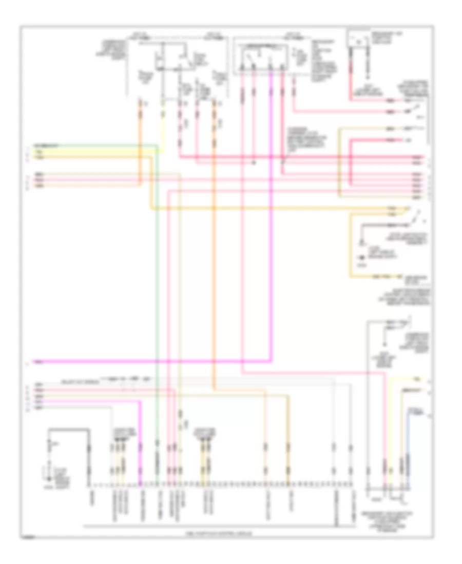
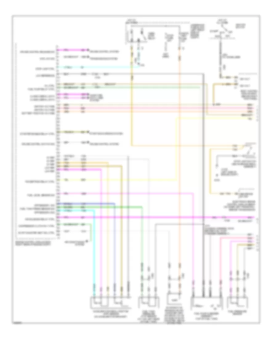
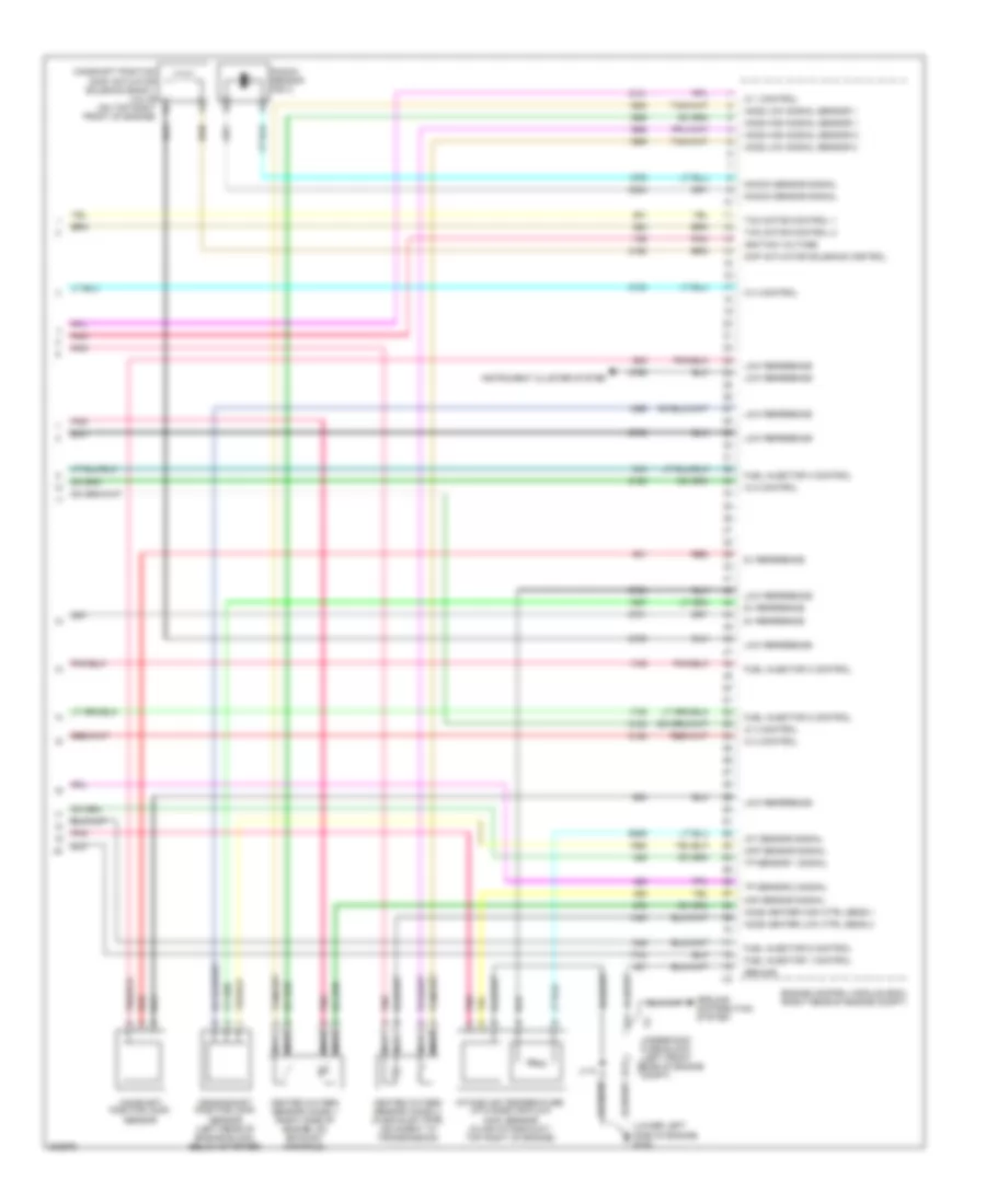
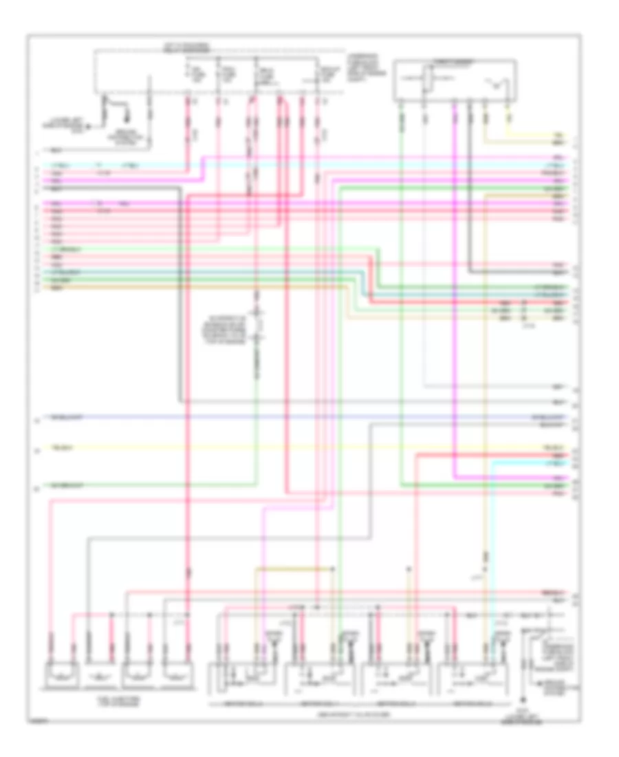
2.9L VIN 9, Engine Performance Wiring Diagram (1 of 5) for GMC Canyon 2011

List of elements for 2.9L VIN 9, Engine Performance Wiring Diagram (1 of 5) for GMC Canyon 2011:
- (a/t) j209
- (behind right kick panel) body control module (bcm)
- (not used)
- 4wd low sig
- 5v reference
- A11
- Acc
- Accelerator pedal position (app) sensor (on accelerator bracket)
- Air conditioning system
- Air solenoid relay ctrl
- App sensor 1 signal
- App sensor 2 signal
- Batt positive voltage
- Canister vent sol ctrl
- Class 2 serial data
- Clstr fuse 10a
- Clutch rly ctrl
- Cnstr vent fuse 10a
- Computer data lines system
- Cruise control system
- Cruise ctrl release sig
- Cruise ctrl sw sig
- Engine control module (ecm) (right rear of engine compt)
- Evaporative emission (evap) canister vent solenoid valve (on side of evap canister, above spare tire)
- Fuel level sens sig
- Fuel pressure sensor
- Fuel pump & sender assembly (top of fuel tank)
- Fuel pump relay ctrl
- Fuel tank pressure (ftp) sensor (at top left rear of fuel tank)
- Hot at all times
- Ign
- Ign volt
- Ignition switch
- Ignition voltage
- Instrument panel cluster (ipc)
- J100 (body harness, 14.5 cm from accelerator pedal position switch breakout)
- J204 (w/ immobilizer)
- J310 (chassis harness, 39 cm before fuel pump & sender assembly)
- Logic
- Low reference
- Mil ctrl
- Mil ind
- Nca
- Off
- Pnk
- Powertrain rly ctrl
- Run
- Serial data
- Start
- Starter enable rly ctrl
- Starting/charging system
- Stop fuse 20a
- Stop lamp ctrl
- Tan
- Tank pressure sens sig
- Transmissions system
- Underhood fuse block (left front side of engine compt)
- Up shift ind
- Vses/ stop relay
- X102
- X104
- X125
- X200
- X201
- X204
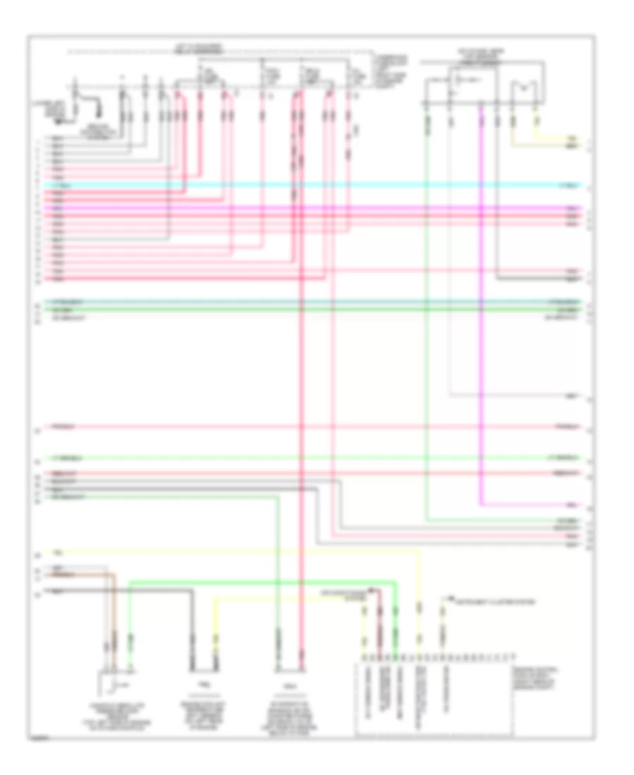
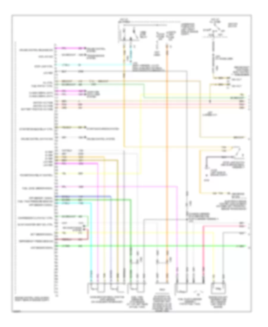
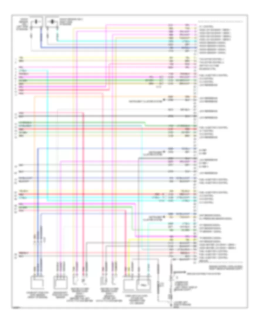
2.9L VIN 9, Engine Performance Wiring Diagram (2 of 5) for GMC Canyon 2011
List of elements for 2.9L VIN 9, Engine Performance Wiring Diagram (2 of 5) for GMC Canyon 2011:
- (if equipped) secondary air injection (air) pump relay
- (in engine harness, 24 cm before generator battery control module breakout) j105
- 5-volt ref
- A red
- Abs brake sw sig
- Air pump fuse 50a
- Air pump relay
- Batt pos volt
- Computer data lines system
- Data bus (+)
- Data bus (-)
- Electronic brake control module (ebcm) (on inner left frame rail, beside transmission)
- Etc fuse 15a
- F11
- Fscm fuse 20a
- Fuel pump flow control module
- G101 (lower left side of engine)
- G103 (lower left side of engine)
- G105
- Ground
- Hot at all times
- Ign volt
- Ignition volt
- J401
- J423
- Jx105 (left side of engine compt)
- Low reference
- Nca
- O2 snsr fuse 15a
- Pcm-b fuse 10a
- Pnk
- Press sens sig
- Pump rel ctrl
- Pump supp volt
- Pwr/ trn relay
- Red
- Secondary air injection (air) pump
- Secondary air injection (air) pump fuse block (if equipped) (right front of engine compt)
- Secondary air injection (air) pump solenoid (if equipped) (upper right side of engine)
- Shield extension
- Stop lamp switch (above brake pedal assembly)
- Tan
- Underhood fuse block (left front side of engine compt)
- X102
- X110
- X125
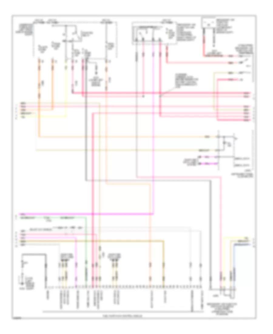
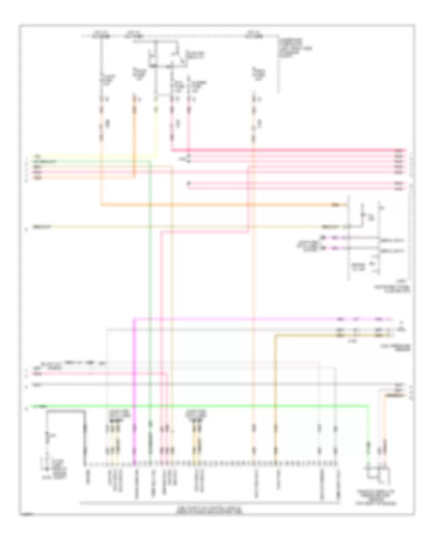
2.9L VIN 9, Engine Performance Wiring Diagram (3 of 5) for GMC Canyon 2011
List of elements for 2.9L VIN 9, Engine Performance Wiring Diagram (3 of 5) for GMC Canyon 2011:
- (on top left of valve cover) ignition coil 1
- (on top left of valve cover) ignition coil 3
- (on top right of valve cover) ignition coil 2
- (on top right of valve cover) ignition coil 4
- (top of engine, attached to fuel rail) fuel injectors
- 5-volt reference
- A pnk
- Air conditioning system
- Air relay control
- Anti-lock brakes system
- Computer data lines system
- Delivered torque
- Duty cycle signal
- Engine control module (ecm) (right rear of engine compt)
- Evap canister purge solenoid control
- Generator
- Generator field
- High speed gmlan
- J104
- Low reference
- Nca
- Park/neutral sig
- Pnk
- Regulator ctrl
- Requested torque signal
- Serial data bus +
- Serial data bus -
- Signal
- Spark plug
- Starting/charging system
- Tan
- X101
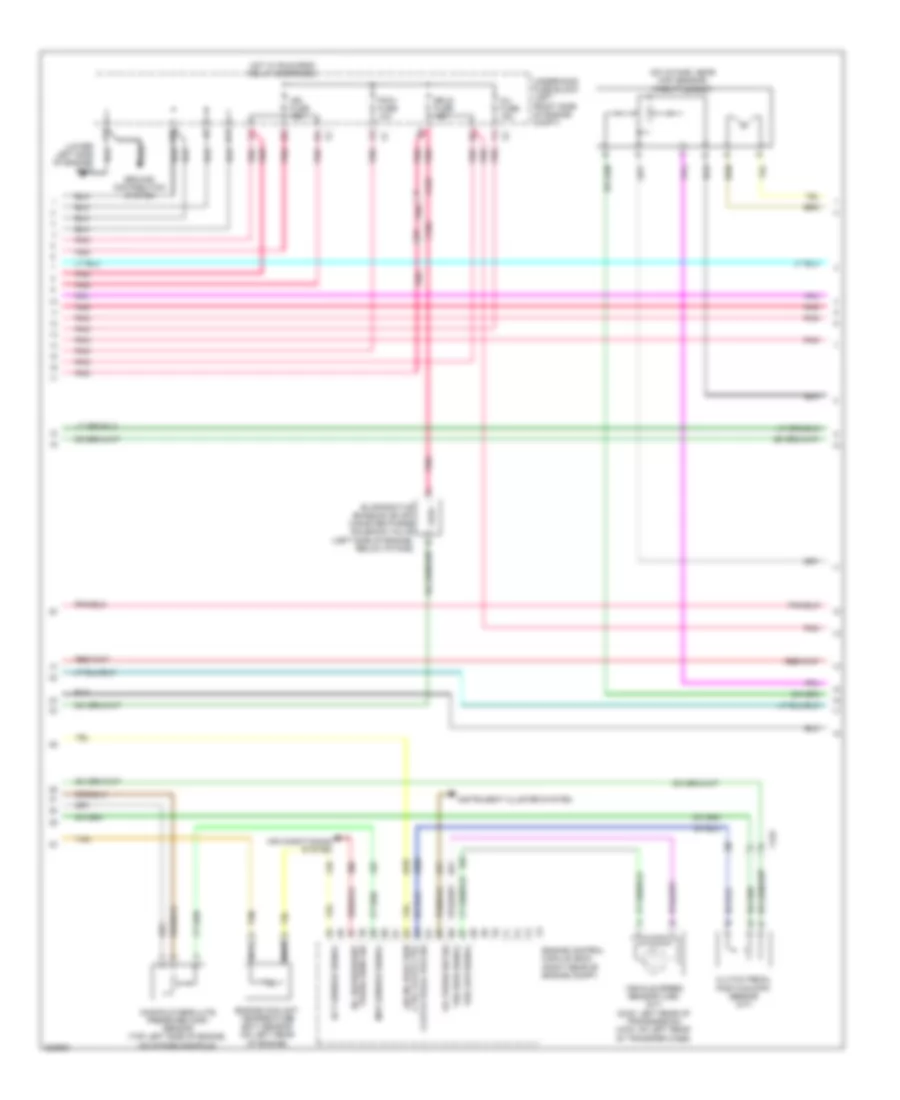
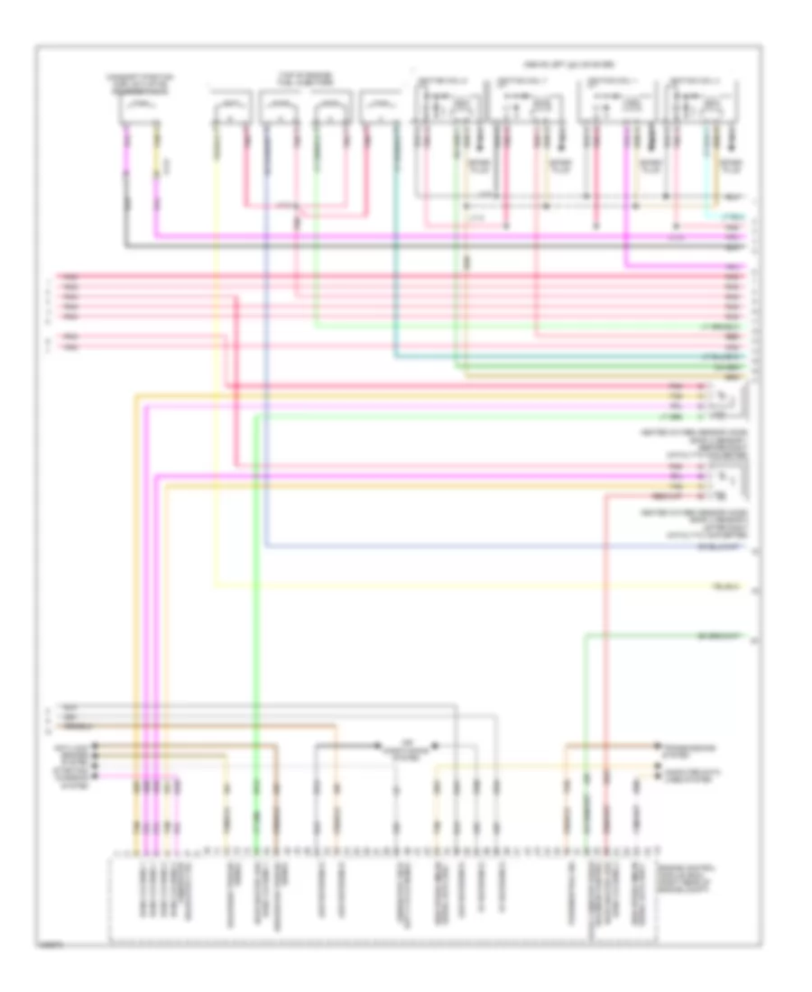
2.9L VIN 9, Engine Performance Wiring Diagram (4 of 5) for GMC Canyon 2011
List of elements for 2.9L VIN 9, Engine Performance Wiring Diagram (4 of 5) for GMC Canyon 2011:
- (lower left side of engine) g103
- (on intake, near map sensor) throttle body
- A/c refrigerant press sens sig
- Air conditioning system
- Air inj reaction
- Clutch pedal pos sig ctrl valve ctrl
- Clutch pedal position (cpp) sensor (m/t)
- D11
- E11
- Ect sensor signal
- Engine control module (ecm) (right rear of engine compt)
- Engine coolant temperature (ect) sensor (on left rear of engine)
- Erls fuse 15a
- Evaporative emission (evap) canister purge solenoid valve (left side of engine, below intake)
- F11
- Ground distribution system
- Hot w/ run/crnk relay energized
- Ign fuse 15a
- Inj fuse 15a
- Instrument cluster system
- Manifold absolute pressure (map) sensor (top left side of engine, on intake manifold)
- Map sensor signal
- Nca
- Oil press sw sig
- Pcm-i fuse 10a
- Pnk
- Tan
- Underhood fuse block (left front side of engine compt)
- Vehicle speed sensor (vss) (m/t) (2wd: left rear of transmission) (4wd: on left rear of transfer case)
- Vss high signal
- Vss low signal
- X102
- X125
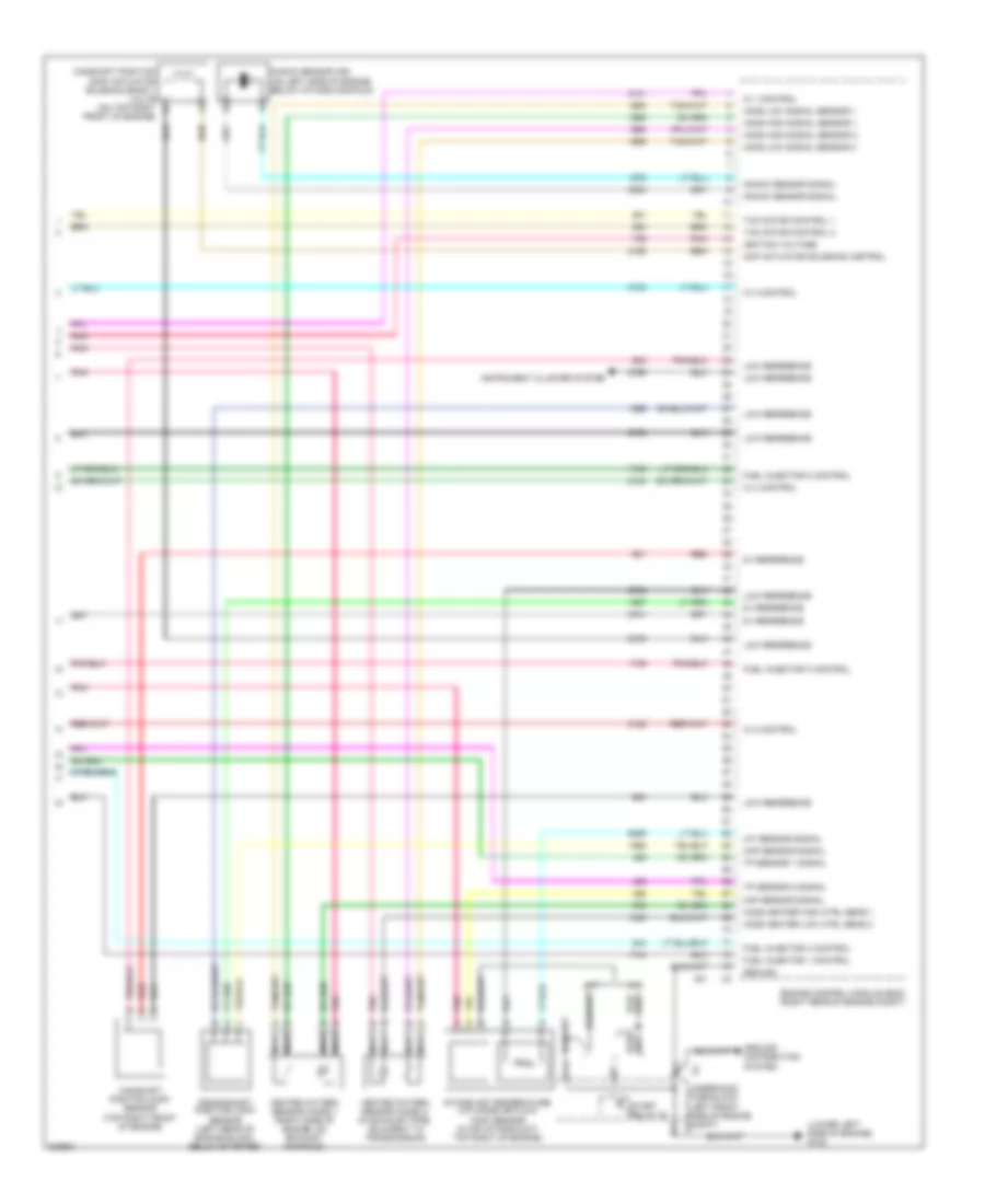
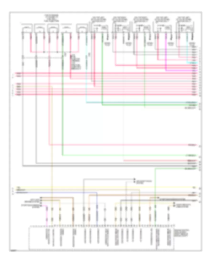
2.9L VIN 9, Engine Performance Wiring Diagram (5 of 5) for GMC Canyon 2011
List of elements for 2.9L VIN 9, Engine Performance Wiring Diagram (5 of 5) for GMC Canyon 2011:
- (lower left side of engine) g102
- 5v reference
- A/t
- A11
- B11
- C11
- Camshaft position (cmp) actuator solenoid bank 1 valve (on top right b
- Camshaft position (cmp) sensor (top right front of engine)
- Ckp sensor signal
- Cmp actuator solenoid control
- Crankshaft position (ckp) sensor (left rear of engine block, below starter)
- Engine control module (ecm) (right rear of engine compt)
- Front of engine)
- Fuel injector 1 control
- Fuel injector 2 control
- Fuel injector 3 control
- Fuel injector 4 control
- Ground
- Ground distribution system
- Heated oxygen sensor (ho2s) 1 (right side of engine, on exhaust manifold)
- Heated oxygen sensor (ho2s) 2 (in exhaust pipe, adjacent to transmission)
- Ho2s heater high ctrl sens 1
- Ho2s heater low ctrl sens 2
- Ho2s high signal sensor 1
- Ho2s high signal sensor 2
- Ho2s low signal sensor 1
- Ho2s low signal sensor 2
- Iat sensor signal
- Ic 1 control
- Ic 2 control
- Ic 3 control
- Ic 4 control
- Ignition voltage
- Instrument cluster system
- Intake air temperature (iat)/mass air flow (maf) sensor (in air intake duct, top right of engine)
- Knock sensor (ks) (on left side of engine, below intake manifold)
- Knock sensor signal
- Low reference
- M/t
- Maf sensor signal
- Nca
- Pnk
- Red
- Start relay 43
- Tac motor control 1
- Tac motor control 2
- Tp sensor 1 signal
- Tp sensor 2 signal
- X2 underhood fuse block (left front side of engine compt) x2
3.7L VIN E
3.7L VIN E, Engine Performance Wiring Diagram (1 of 5) for GMC Canyon 2011
List of elements for 3.7L VIN E, Engine Performance Wiring Diagram (1 of 5) for GMC Canyon 2011:
- (not used)
- 4wd low sig
- 5v ref
- A11
- Abs brake sw sig
- Acc
- Accelerator pedal position (app) sensor (on accelerator bracket)
- Air conditioning system
- Air solenoid relay ctrl
- App sensor 1 sig
- App sensor 2 sig
- Battery positive voltage
- Body control module (bcm) (behind right
- Class 2 serial data
- Cnstr vent fuse 10a
- Compressor clutch rly ctrl
- Computer data lines system
- Cruise control release sig
- Cruise control switch sig
- Cruise control system
- Electronic brake control module (ebcm) (on inner left frame rail, beside transmission)
- Engine control module (ecm) (right rear of engine compt)
- Evap canister vent sol ctrl
- Evaporative emission (evap) canister vent solenoid valve (on side of evap canister, above spare tire)
- Fuel level sensor sig
- Fuel pressure sensor
- Fuel pump & sender assembly (top of fuel tank)
- Fuel pump relay ctrl
- Fuel tank press sensor sig
- Fuel tank pressure (ftp) sensor (at top left rear of fuel tank)
- G105
- Hot at all times
- Ign volt
- Ignition switch
- Ignition voltage
- J100
- J204 (w/ immobilizer)
- J209
- J310 (chassis harness, 39 cm before fuel pump & sender assembly)
- Jx105 (left side of engine compt)
- Kick panel)
- Low ref
- Low reference
- Mil ctrl
- Nca
- Off
- Pnk
- Powertrain relay ctrl
- Run
- Start
- Starter enable relay ctrl
- Starting/charging system
- Stop fuse 20a
- Stop lamp ctrl
- Stop lamp switch (above brake pedal assembly)
- Tan
- Transmissions system
- Underhood fuse block (left front side of engine compt)
- Vses/ stop relay
- X102
- X104
- X125
- X126
- X201
- X204
3.7L VIN E, Engine Performance Wiring Diagram (2 of 5) for GMC Canyon 2011
List of elements for 3.7L VIN E, Engine Performance Wiring Diagram (2 of 5) for GMC Canyon 2011:
- (if equipped) secondary air injection (air) pump relay
- (in engine harness, 24 cm before generator battery control module breakout) j105
- 5-volt ref
- A red
- Air pump fuse 50a
- Air pump relay
- Batt pos volt
- Clstr fuse 10a
- Computer data lines system
- Data bus (+)
- Data bus (-)
- Etc fuse 15a
- F11
- Fscm fuse 20a
- Fuel pump flow control module
- G101 (lower left side of engine)
- G103 (lower left side of engine)
- G105
- Ground
- Hot at all times
- Ign volt
- Ignition volt
- Instrument panel cluster (ipc)
- J401
- J423
- Jx105 (left side of engine compt)
- Logic
- Low reference
- Mil ind
- Nca
- O2 snsr fuse 15a
- Pcm-b fuse 10a
- Pnk
- Press sens sig
- Pump rel ctrl
- Pump supp volt
- Pwr/trn relay
- Red
- Secondary air injection (air) pump (lower right front of engine compt)
- Secondary air injection (air) pump fuse block (if equipped) (right front of engine compt)
- Secondary air injection (air) pump solenoid (if equipped) (upper right side of engine)
- Serial data
- Shield extension
- Tan
- Underhood fuse block (left front side of engine compt)
- X102
- X110
- X125
- X200
3.7L VIN E, Engine Performance Wiring Diagram (3 of 5) for GMC Canyon 2011
List of elements for 3.7L VIN E, Engine Performance Wiring Diagram (3 of 5) for GMC Canyon 2011:
- (on top left of valve cover) ignition coil 1
- (on top left of valve cover) ignition coil 3
- (on top left of valve cover) ignition coil 5
- (on top right of valve cover) ignition coil 2
- (on top right of valve cover) ignition coil 4
- (top of engine, attached to fuel rail) fuel injectors
- 5v reference
- A pnk
- Air conditioning system
- Air relay control
- Anti-lock brakes system
- Computer data lines system
- Delivered torque
- Duty cycle signal
- Engine control module (ecm) (right rear of engine compt)
- Evap canister purge
- Generator
- Generator field
- High speed gmlan
- J104 pnk (fuel injector harness, 4 cm from fuel injector 4 breakout)
- Low reference
- Nca
- Park/neutral sig
- Pnk
- Regulator ctrl
- Requested torque signal
- Serial data bus +
- Serial data bus -
- Signal
- Solenoid control
- Spark plug
- Starting/charging system
- Tan
- X101
3.7L VIN E, Engine Performance Wiring Diagram (4 of 5) for GMC Canyon 2011
List of elements for 3.7L VIN E, Engine Performance Wiring Diagram (4 of 5) for GMC Canyon 2011:
- (lower left side of engine) g103
- (on intake, near map sensor) throttle body
- A/c refrigerant press sens sig
- Air conditioning system
- Air injection reaction ctrl valve ctrl
- D11
- E11
- Ect sensor signal
- Engine control module (ecm) (right rear of engine compt)
- Engine coolant temperature (ect) sensor (on left rear of engine)
- Erls fuse 15a
- Evaporative emission (evap) canister purge solenoid valve (left side of engine, below intake)
- F11
- Ground distribution system
- Hot w/ run/crnk relay energized
- Ign fuse 15a
- Inj fuse 15a
- Instrument cluster system
- Manifold absolute pressure (map) sensor (top left side of engine, on intake manifold)
- Map sensor signal
- Nca
- Oil press sw sig
- Pcm-i fuse 10a
- Pnk
- Underhood fuse block (left front side of engine compt)
- X101
- X102
- X125
3.7L VIN E, Engine Performance Wiring Diagram (5 of 5) for GMC Canyon 2011
List of elements for 3.7L VIN E, Engine Performance Wiring Diagram (5 of 5) for GMC Canyon 2011:
- (lower left side of engine) g102
- 5v reference
- A11
- B11
- Camshaft position (cmp) actuator solenoid bank 1 valve (on top right b
- Camshaft position (cmp) sensor
- Ckp sensor signal
- Cmp actuator solenoid control
- Crankshaft position (ckp) sensor (left rear of engine block, below starter)
- Engine control module (ecm) (right rear of engine compt)
- Front of engine)
- Fuel injector 1 control
- Fuel injector 2 control
- Fuel injector 3 control
- Fuel injector 4 control
- Fuel injector 5 control
- Ground
- Ground distribution system
- Heated oxygen sensor (ho2s) 1 (right side of engine, on exhaust manifold)
- Heated oxygen sensor (ho2s) 2 (in exhaust pipe, adjacent to transmission)
- Ho2s heater high ctrl sens 1
- Ho2s heater low ctrl sens 2
- Ho2s high signal sensor 1
- Ho2s high signal sensor 2
- Ho2s low signal sensor 1
- Ho2s low signal sensor 2
- Iat sensor signal
- Ic 1 control
- Ic 2 control
- Ic 3 control
- Ic 4 control
- Ic 5 control
- Ignition voltage
- Instrument cluster system
- Intake air temperature (iat)/mass air flow (maf) sensor (in air intake duct, top right of engine)
- J110
- Knock sensor (ks) 2
- Knock sensor signal
- Low reference
- Maf sensor signal
- Nca
- Pnk
- Red
- Tac motor control 1
- Tac motor control 2
- Tp sensor 1 signal
- Tp sensor 2 signal
- X2 underhood fuse block (left front x2 side of engine compt)
5.3L VIN P
5.3L VIN P, Engine Performance Wiring Diagram (1 of 5) for GMC Canyon 2011
List of elements for 5.3L VIN P, Engine Performance Wiring Diagram (1 of 5) for GMC Canyon 2011:
- (behind right kick panel) body control module (bcm)
- (not used)
- 4wd low sig
- 5v ref
- A11
- Abs brake sw sig
- Acc
- Accelerator pedal position (app) sensor (on accelerator bracket)
- Air conditioning system
- App sensor 1 signal
- App sensor 2 signal
- Battery positive voltage
- Class 2 serial data
- Cnstr vent fuse 10a
- Compressor clutch rly ctrl
- Computer data lines system
- Cruise control release sig
- Cruise control switch sig
- Cruise control system
- Ect sensor signal
- Electronic brake control module (ebcm) (on inner left frame rail, beside transmission)
- Engine control module (ecm) (right rear of engine compt)
- Engine coolant temperature (ect) sensor (left side of engine)
- Evap canister vent sol ctrl
- Evaporative emission (evap) canister vent solenoid valve (on side of evap canister, above spare tire)
- Fuel level sensor signal
- Fuel pmp rly ctrl
- Fuel pump & sender assembly (top of fuel tank)
- Fuel tank pressure (ftp) sensor (at top left rear of fuel tank)
- Fuel tank pressure sens sig
- G105
- Hot at all times
- Ign volt
- Ignition switch
- Ignition voltage
- J100 (body harness, 14.5 cm from accelerator pedal position switch breakout)
- J204 (w/ immobilizer)
- J207 (4 speed a/t)
- Jx105 (left side of engine compt)
- Low ref
- Map sensor signal
- Mil ctrl
- Nca
- Off
- Pnk
- Powertrain relay control
- Pump & sender assembly) j310
- Refrigerant press sens sig
- Run
- Start
- Starter enable relay ctrl
- Starting/charging system
- Stop fuse 20a
- Stop lamp ctrl
- Stop lamp switch (above brake pedal assembly)
- Tan
- Transmissions system
- Underhood fuse block (left front side of engine compt)
- Vses/ stop relay
- X102
- X104
- X201
- X204
5.3L VIN P, Engine Performance Wiring Diagram (2 of 5) for GMC Canyon 2011
List of elements for 5.3L VIN P, Engine Performance Wiring Diagram (2 of 5) for GMC Canyon 2011:
- 5-volt ref
- Batt pos volt
- Clstr fuse 10a
- Computer data lines system
- Data bus (+)
- Data bus (-)
- Engine oil ind
- Etc fuse 15a
- Fscm fuse 20a
- Fuel pressure sensor
- Fuel pump flow control module (rear of frame above spare tire)
- G105
- Ground
- Hot at all times
- Ign volt
- Ignition volt
- Instrument panel cluster (ipc)
- J106
- J401
- J423
- Jx105 (left side of engine compt)
- Logic
- Low ref
- Manifold absolute pressure (map) sensor (top front of engine)
- Mil ind
- O2 snsr fuse 15a
- Pcm-b fuse 10a
- Pnk
- Press sens sig
- Pump rel ctrl
- Pump supp volt
- Pwr/trn relay 81
- Serial data
- Shld extension
- Tan
- Underhood fuse block (left front side of engine compt)
- X125
- X126
- X200
5.3L VIN P, Engine Performance Wiring Diagram (3 of 5) for GMC Canyon 2011
List of elements for 5.3L VIN P, Engine Performance Wiring Diagram (3 of 5) for GMC Canyon 2011:
- (above left valve cover)
- (top of engine) fuel injectors
- 5v reference
- A pnk
- Air conditioning system
- Anti-lock brakes system
- Bank 2 & sens 1
- Bank 2 & sens 2
- C red
- Camshaft position (cmp) actuator solenoid valve
- Computer data lines system
- D pnk
- Delivered torque
- Duty cycle signal
- Engine control module (ecm) (right rear of engine compt)
- Evap canister purge
- Generator field
- Heated oxygen sensor (ho2s) bank 2 sensor 1 (before right catalytic converter)
- Heated oxygen sensor (ho2s) bank 2 sensor 2 (after right catalytic converter)
- High speed gmlan
- Ho2s heater low
- Ignition coil 1
- Ignition coil 3
- Ignition coil 5
- Ignition coil 7
- J112
- J113
- J114
- J115
- Low reference
- Nca
- Park/neutral sig
- Pnk
- Red
- Regulator ctrl generator
- Requested torque signal
- Serial data bus +
- Serial data bus -
- Signal
- Solenoid control
- Spark plug
- Starting/ charging system
- Tan
- Transmissions system
- X113
5.3L VIN P, Engine Performance Wiring Diagram (4 of 5) for GMC Canyon 2011
List of elements for 5.3L VIN P, Engine Performance Wiring Diagram (4 of 5) for GMC Canyon 2011:
- (above right valve cover)
- (lower left side of engine) g103
- Bck/up fuse 15a
- C8 pnk
- D11
- E11
- Erls fuse 15a
- Evaporative emission (evap) canister purge solenoid valve (top of engine)
- F11
- Fuel injectors (top of engine)
- G103 (lower left side of engine)
- Ground distribution system
- Hot w/ run/crnk relay energized
- Ign fuse 15a
- Ignition coil 2
- Ignition coil 4
- Ignition coil 6
- Ignition coil 8
- J111
- J116
- J117
- J118
- Nca
- P pnk
- Pcm-i fuse 10a
- Pnk
- Pnk a
- Pnk d
- Red
- Red c
- Spark plug
- Throttle body
- Underhood fuse block (left front side of engine compt)
- X102
- X112
- X115
- X125
5.3L VIN P, Engine Performance Wiring Diagram (5 of 5) for GMC Canyon 2011
List of elements for 5.3L VIN P, Engine Performance Wiring Diagram (5 of 5) for GMC Canyon 2011:
- (lower left side of engine) g102
- 5v ref
- 5v ref 1
- 5v ref 2
- A11
- B11
- Camshaft position (cmp) sensor (front of engine)
- Ckp sensor signal
- Cmp sensor signal
- Crankshaft position (ckp) sensor
- Engine control module (ecm) (right rear of engine compt)
- Fuel injector 1 control
- Fuel injector 2 control
- Fuel injector 3 control
- Fuel injector 4 control
- Fuel injector 5 control
- Fuel injector 6 control
- Fuel injector 7 control
- Fuel injector 8 control
- Ground
- Ground distribution system
- Heated oxygen sensor (ho2s) bank 1 sensor 1 (before the left catalytic converter)
- Heated oxygen sensor (ho2s) bank 1 sensor 2 (after left catalytic converter)
- Ho2s heater low bank 1 sens 1
- Ho2s heater low bank 1 sens 2
- Ho2s high sig bank 1 sens 1
- Ho2s high sig bank 1 sens 2
- Ho2s low sig bank 1 sens 1
- Ho2s low sig bank 1 sens 2
- Iat sensor signal
- Ic 1 control
- Ic 2 control
- Ic 3 control
- Ic 4 control
- Ic 5 control
- Ic 6 control
- Ic 7 control
- Ic 8 control
- Ignition voltage
- Instrument cluster system
- J110 (a/t)
- Knock sensor (ks) 1 (left side of engine) b
- Knock sensor (ks) 2 (right side of engine)
- Knock sensor 1 signal
- Knock sensor 2 signal
- Low reference
- Maf sensor signal
- Mass air flow (maf)/ intake air temperature (iat) sensor
- Oil pressure sensor signal
- Pnk
- Red
- Solenoid ctrl
- Tac motor control 1
- Tac motor control 2
- Tan
- Tp sensor 1 signal
- Tp sensor 2 signal
- Underhood fuse block (left front side of engine compt) x2
- X112
- X113