ENGINE PERFORMANCE
3.5L
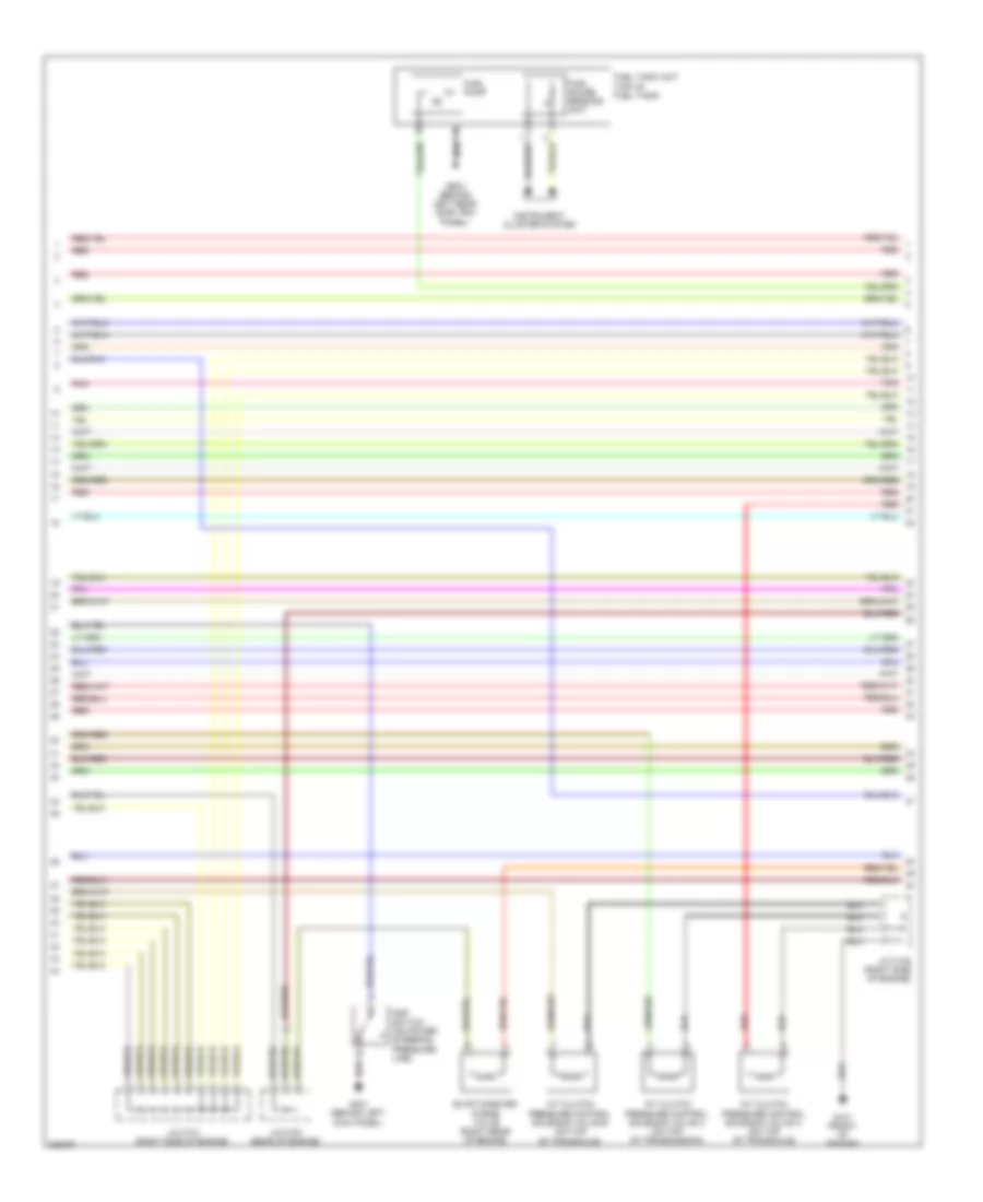
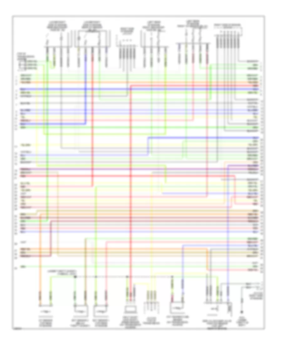
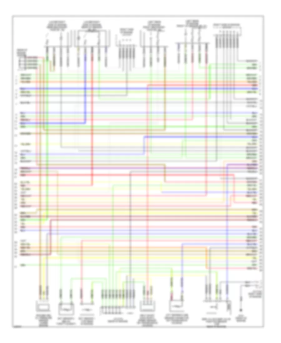
3.5L, Engine Performance Wiring Diagram, EX-L (1 of 7) for Honda Odyssey Touring 2010

List of elements for 3.5L, Engine Performance Wiring Diagram, EX-L (1 of 7) for Honda Odyssey Touring 2010:
- (front of engine) g101
- (on brake pedal bracket) brake pedal position switch
- (under left side of dash) j/c c501
- (under middle of vehicle) evap canister vent shut valve
- A10
- A11
- A12
- A13
- A14
- A15
- A16
- A17
- A18
- A19
- A20
- A21
- A22
- A23
- A24
- A25
- A26
- A27
- A28
- A29
- A30
- A31
- A32
- A33
- A34
- A35
- A36
- A37
- A38
- A39
- A40
- A41
- A42
- A43
- A44
- A45
- A46
- A47
- A48
- A49
- Acc
- Air conditioning system
- Air conditioning system computer data lines system
- Anti-theft system
- Apsa
- Apsb
- Atp-p
- B10
- B11
- B12
- B13
- B14
- B15
- B16
- B17
- B18
- B19
- B20
- B21
- B22
- B23
- B24
- B25
- Barometer sensor
- Bksw
- Bkswnc
- Can-h
- Can-l
- Ckpout
- Cmpout
- Computer data lines system
- Cruise control system
- Cssama
- Cssamc
- D3 switch
- D3 switch/ park pin switch/ a/t gear position indicator panel light (d3 switch/ park pin switch: under left side of dash)
- D3sw
- Driver's under-dash fuse/relay box (behind left kick panel)
- Eld
- Etcsrly
- Fanh
- Fanl
- Ftp
- Fuse 15a
- Fuse 20a
- G501 (under left side of dash)
- Hot at all times
- Hot in on or start
- Igp
- Igpls3
- Igpls4
- Igpls5
- Igpls6
- Imo fpr
- Imocd
- Inj1
- Inj2
- Inj3
- Inj4
- Inj5
- Inj6
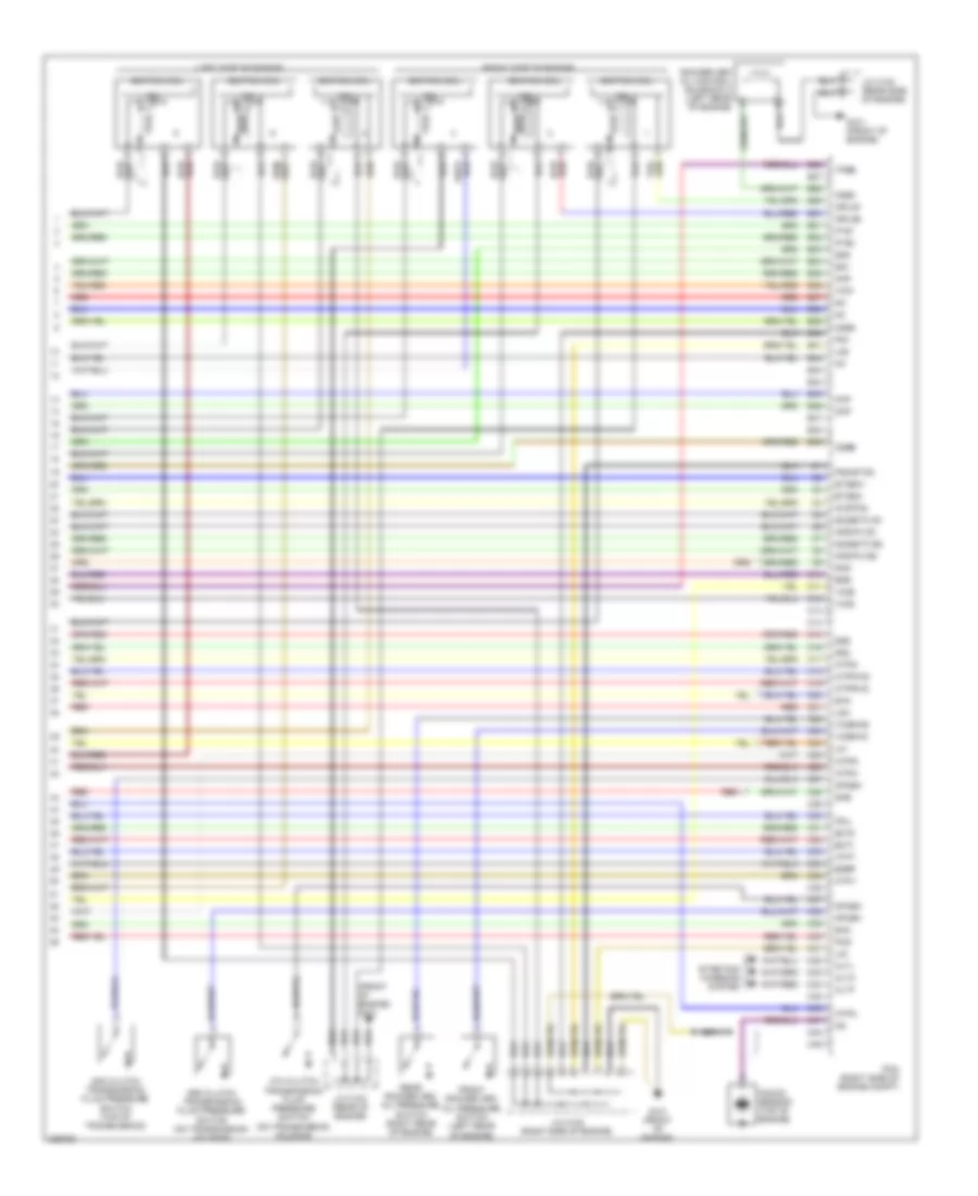
- Injectors (injectors 1, 2 & 3: top right side of engine) (injectors 4, 5 & 6: top left side of engine)
- J/c c102 (right side of engine)
- J/c c103 (rear of engine)
- Lg3
- Lsb
- Lsc
- Met-inh
- Mrly
- Navigation system
- Nca
- Nep
- Pcm (right side of engine compt)
- Pdsw
- Pg2
- Pnk
- Psp sw
- Red
- Scs
- Sg3
- Sg4
- Shift interlock system
- Sho2s b1
- Sho2s b2
- Sls
- Sound systems
- Starting/charging system
- Sts
- Sub rly
- Tpsa
- Under-hood fuse/relay box (right rear of engine compt)
- Vbsol1
- Vbsol2
- Vcc3
- Vcc4
- Vcc5
- Vcent b1
- Vcent b2
- Vg+
- Vg-
- Vs b1
- Vs b2
- Vssout
- Vsv
- Wen
- X16
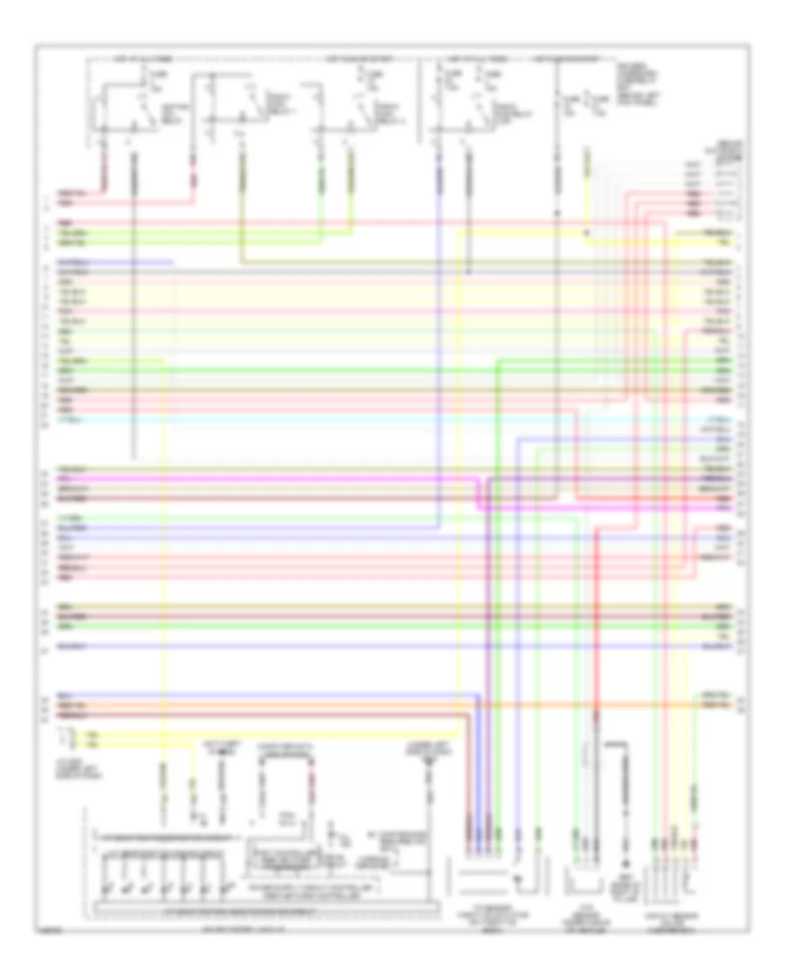
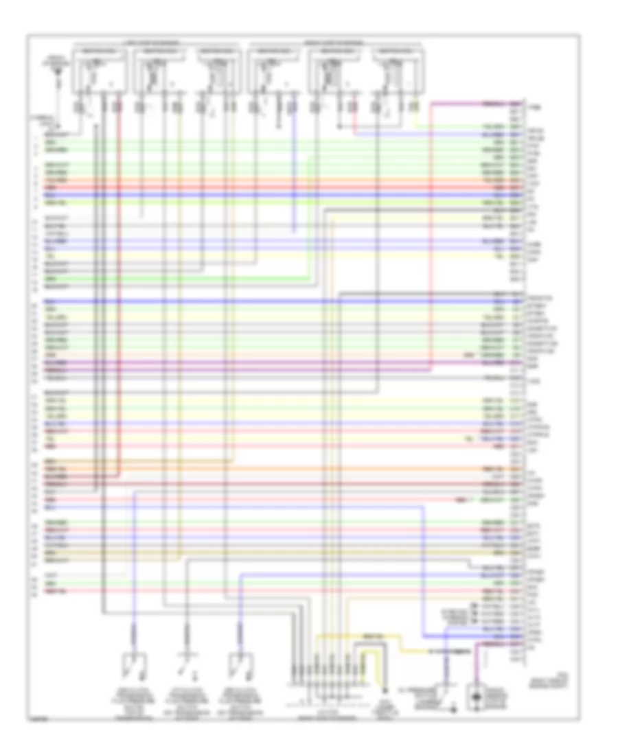
3.5L, Engine Performance Wiring Diagram, EX-L (2 of 7) for Honda Odyssey Touring 2010
List of elements for 3.5L, Engine Performance Wiring Diagram, EX-L (2 of 7) for Honda Odyssey Touring 2010:
- A/t clutch pressure control solenoid valve a (on top of transaxle)
- A/t clutch pressure control solenoid valve b (on top of transaxle)
- A/t clutch pressure control solenoid valve c (on top of transmission)
- Evap canister purge valve (right rear of engine)
- Fuel gauge sending unit
- Fuel pump
- Fuel tank unit (top of fuel tank)
- G101 (front of engine)
- G401 (behind left kick panel)
- G603 (behind left rear side trim panel)
- Instrument cluster system
- J/c c101 (right side of engine)
- J/c c102 (right side of engine)
- J/c c103 (rear of engine)
- Pnk
- Psp switch (on power steering pressure line)
- Red
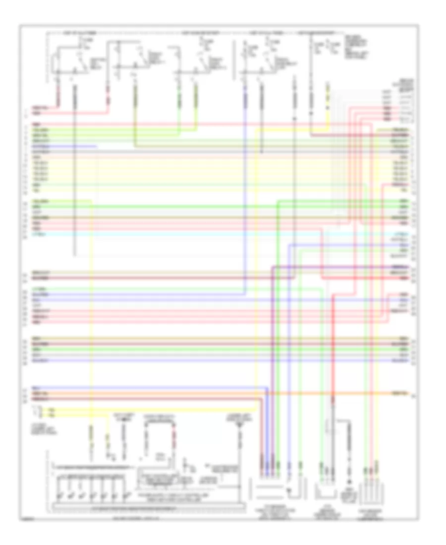
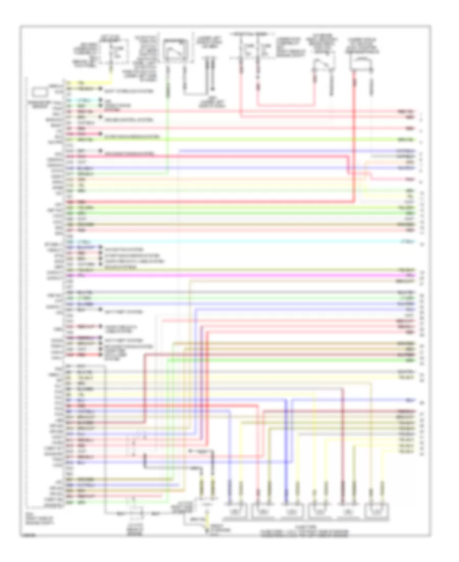
3.5L, Engine Performance Wiring Diagram, EX-L (3 of 7) for Honda Odyssey Touring 2010
List of elements for 3.5L, Engine Performance Wiring Diagram, EX-L (3 of 7) for Honda Odyssey Touring 2010:
- (behind glove box) j/c c407
- (under left side of dash) g502
- A/t gear position detection circuit
- A/t gear position dimming circuit
- A/t gear position indicator driver circuit
- A21
- A23
- A24
- Anti-theft system
- Braided wire
- Computer data lines system
- D10
- Drive circuit
- Driver's underdash fuse/relay box (behind left kick panel)
- E13
- Fast controller area network transceiver
- Ftp sensor (under middle of vehicle)
- Fuse 15a
- Fuse 7.5a
- G651 (base of right "b" pillar)
- Gauge control module
- Hot at all times
- Hot in on or start
- Ignition coil relay
- J/c c503 (under left side of dash)
- Maf/iat sensor (on air cleaner box)
- Maintenance required ind (ex-l)
- Mil ind
- Pgm-fi main relay 1
- Pgm-fi main relay 2
- Pgm-fi sub relay (laf)
- Pnk
- Red
- Tp sensor/ throttle actuator (on throttle body)
- Warning drive ind
- X31
- X32
- X34
- X36
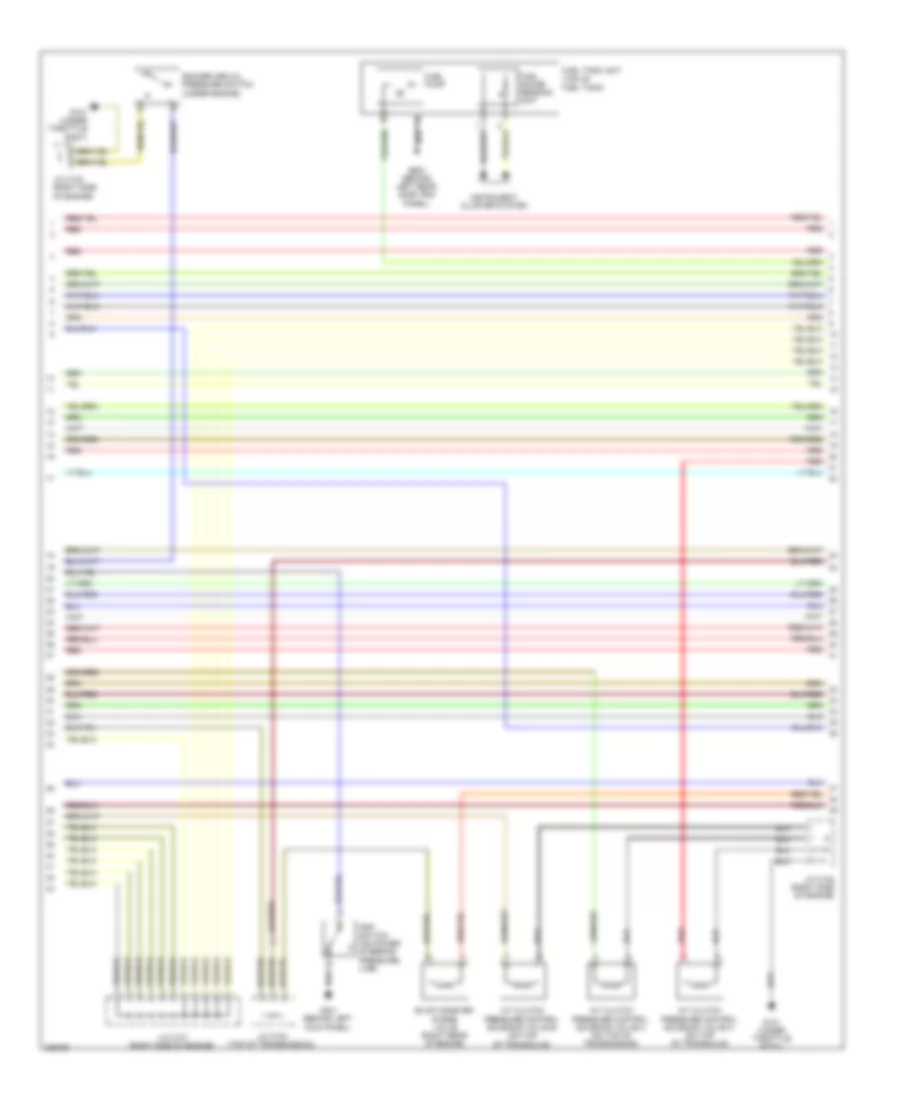
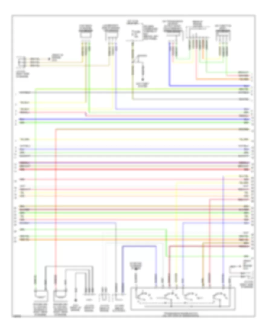
3.5L, Engine Performance Wiring Diagram, EX-L (4 of 7) for Honda Odyssey Touring 2010
List of elements for 3.5L, Engine Performance Wiring Diagram, EX-L (4 of 7) for Honda Odyssey Touring 2010:
- (not used)
- (under left side of dash) app sensor
- Acm control relay
- Acm control unit (under right side of dash)
- Active noise control unit (ex-l: under right side of dash) (touring: under middle of dash)
- Auxiliary under-hood fuse box (right rear of engine compt)
- B10
- Canh
- Canl
- Computer data lines system
- Crk
- Cssam1
- Cssam2
- Ects control relay
- Front acm actuator (under front of engine compt)
- Fuse 10a
- Fuse 3 15a
- G202 (right side of engine compt)
- G504 (behind right end of dash)
- Hot at all times
- Ig1
- Igsol
- J13
- Passenger's under-dash fuse/relay box (behind right kick panel)
- Pnk
- Rear acm actuator (under middle rear of engine compt)
- Red
- Scp
- Scp2
- Shift control solenoid valve a
- Shift control solenoid valve b
- Shift control solenoid valve c
- Shift control solenoid valve d
- Solfm
- Solfp
- Solrm
- Solrp
- Solry
- Tdc
- Touring ex-l
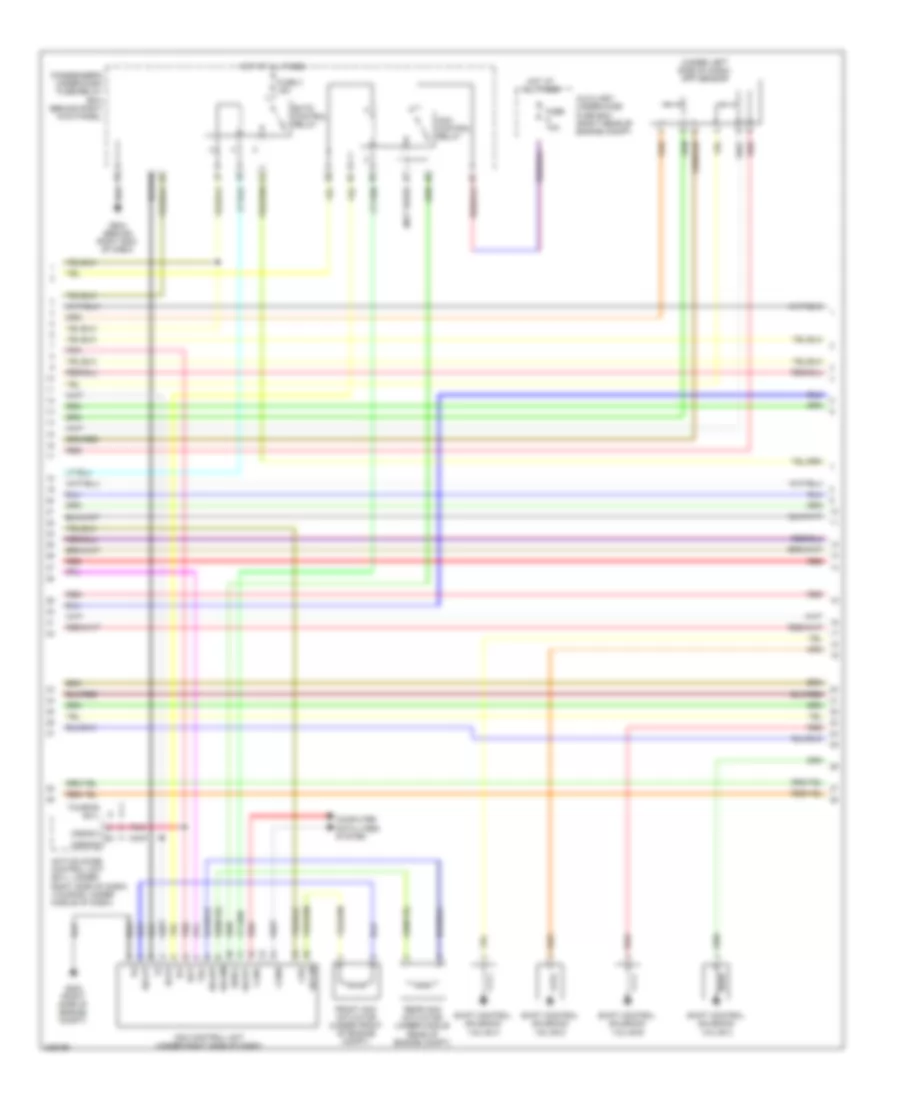
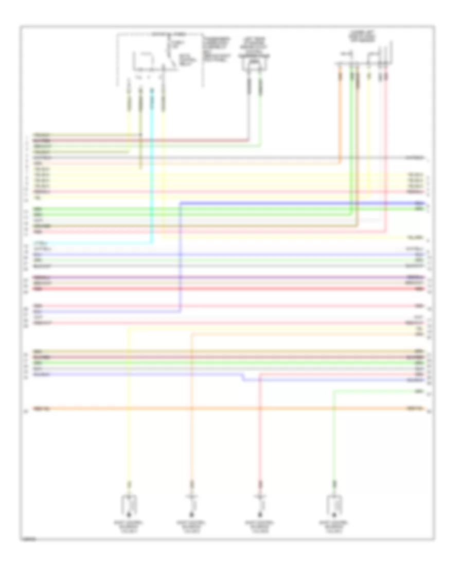
3.5L, Engine Performance Wiring Diagram, EX-L (5 of 7) for Honda Odyssey Touring 2010
List of elements for 3.5L, Engine Performance Wiring Diagram, EX-L (5 of 7) for Honda Odyssey Touring 2010:
- (front of engine) g101
- (lower right side of engine) ckp sensor
- (on throttle body) map sensor
- (on transmission housing) output shaft (countershaft) speed sensor
- (rear of engine) j/c c104
- (top front of engine) cmp sensor
- Anti-theft system
- Canada
- Driver's under-dash fuse/relay box (behind left kick panel)
- Fuse 15a
- G101 (front of engine)
- Hot in on or start
- J/c c102 (right side of engine)
- J/c c103 (rear of engine)
- J/c c104 (rear of engine)
- J/c c405 (behind glove box)
- Red
- Rocker arm oil control solenoid a (right rear of engine)
- Rocker arm oil control solenoid b (right rear of engine)
- Starting/ charging system
- Transmission range switch (on left side of transmission)
- X38
3.5L, Engine Performance Wiring Diagram, EX-L (6 of 7) for Honda Odyssey Touring 2010
List of elements for 3.5L, Engine Performance Wiring Diagram, EX-L (6 of 7) for Honda Odyssey Touring 2010:
- (left rear of engine) front a/f sensor (b2, s1)
- (left rear of engine) front secondary ho2s (b2, s2)
- (lower right side of engine) rear a/f sensor (b1, s1)
- (lower right side of engine) rear secondary ho2s (b1, s2)
- (rear of engine) j/c c104
- (right side of engine) j/c c101
- Atf temperature sensor connector (on transmission housing)
- Ect sensor 1 (top rear of engine)
- Ect sensor 2 (below throttle body)
- Egr valve & egr valve position sensor (top rear of engine)
- G101 (front of engine)
- Input shaft (main shaft) speed sensor (on transmission housing)
- J/c c102 (right side of engine)
- J/c c104 (rear of engine)
- Pnk
- Red
- Rocker arm oil pressure sensor (under engine)
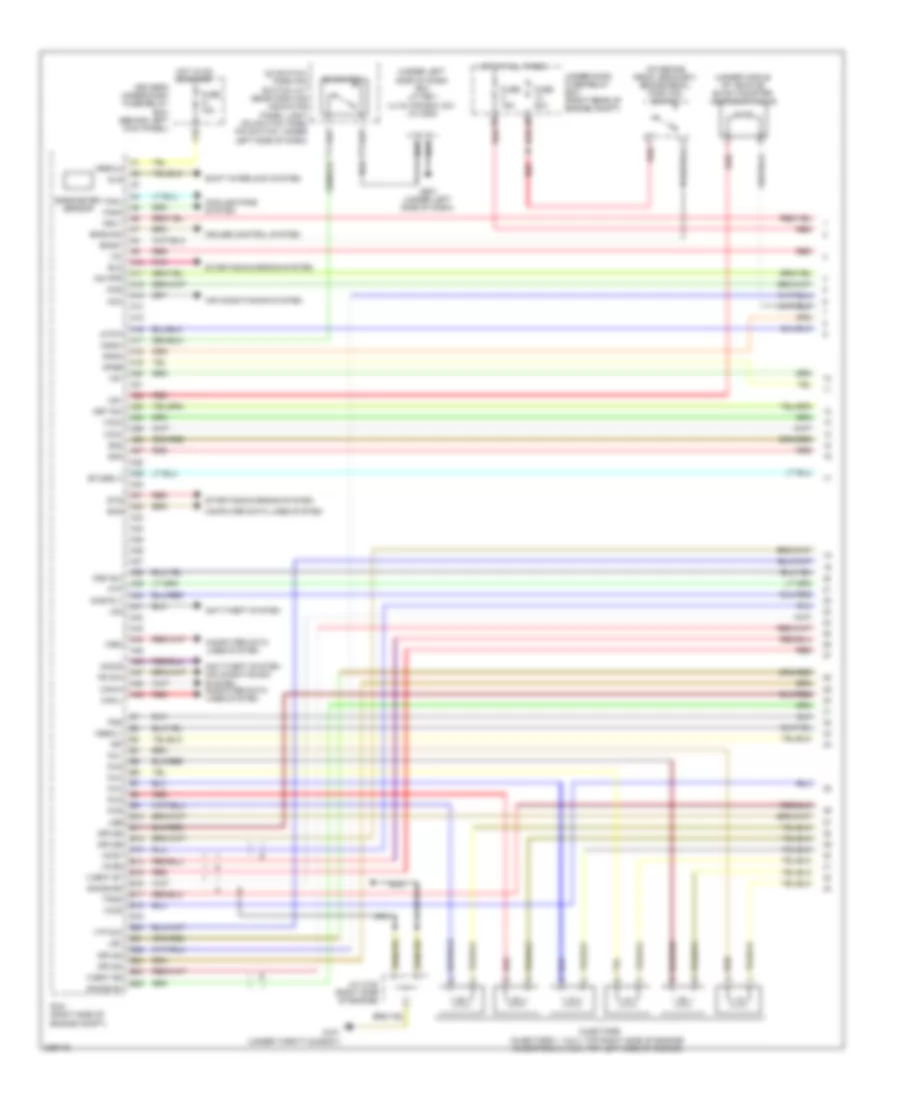
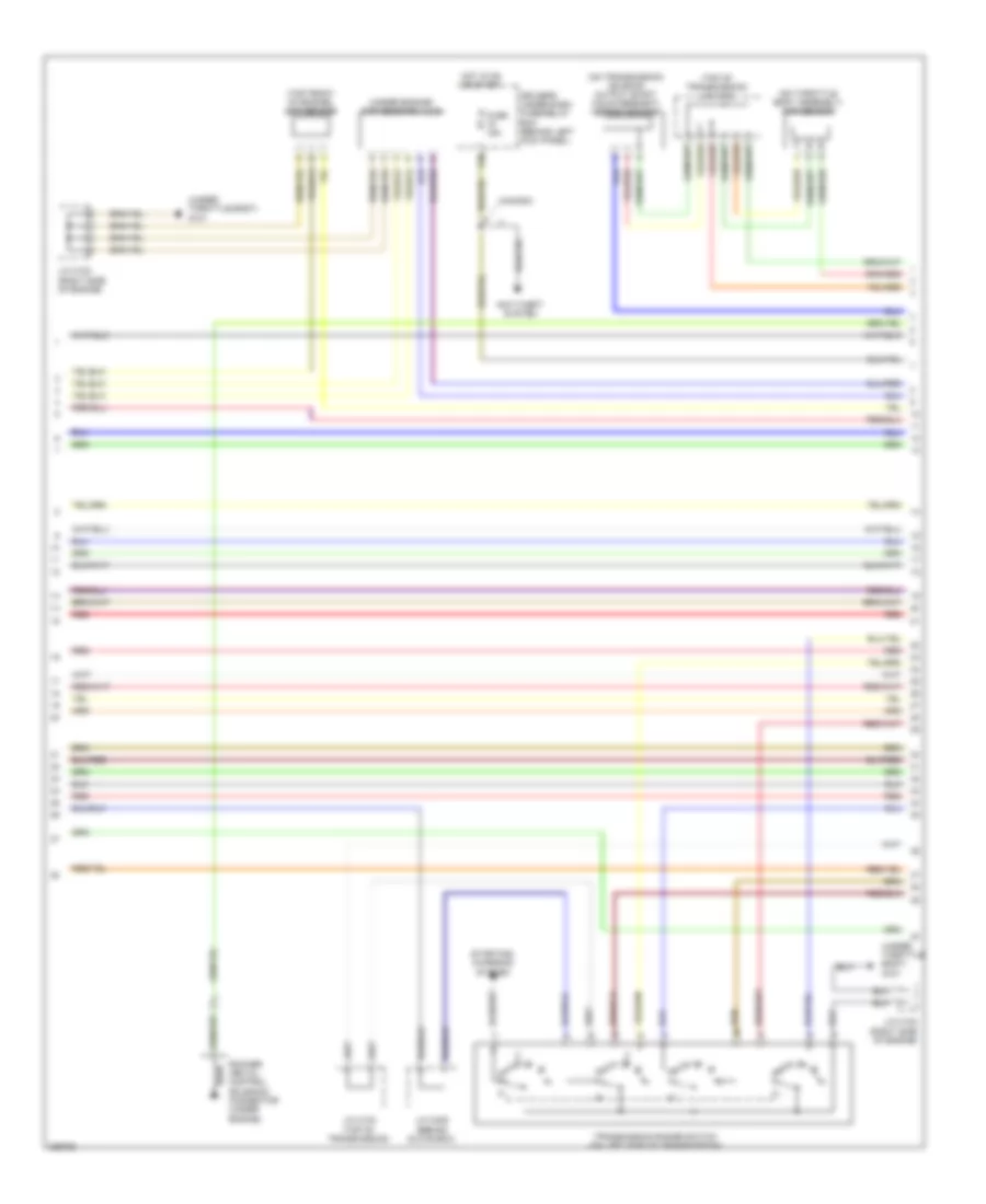
3.5L, Engine Performance Wiring Diagram, EX-L (7 of 7) for Honda Odyssey Touring 2010
List of elements for 3.5L, Engine Performance Wiring Diagram, EX-L (7 of 7) for Honda Odyssey Touring 2010:
- (front of engine) g101
- (left side of engine)
- (right side of engine)
- 2nd clutch transmission fluid pressure switch (top of transmission)
- 3rd clutch transmission fluid pressure switch (on transmission housing)
- 4th clutch transmission fluid pressure switch (on transmission housing)
- Afshtc b1
- Afshtc b2
- Altc
- Altf
- Altl
- Atft
- Atp-1
- Atp-2
- Atp-d
- Atp-fwd
- Atp-n
- Atp-r
- Atp-rvs
- B26
- B27
- B28
- B29
- B30
- B31
- B32
- B33
- B34
- B35
- B36
- B37
- B38
- B39
- B40
- B41
- B42
- B43
- B44
- B45
- B46
- B47
- B48
- B49
- C10
- C11
- C12
- C13
- C14
- C15
- C16
- C17
- C18
- C19
- C20
- C21
- C22
- C23
- C24
- C25
- C26
- C27
- C28
- C29
- C30
- C31
- C32
- C33
- C34
- C35
- C36
- C37
- C38
- C39
- C40
- C41
- C42
- C43
- C44
- C45
- C46
- C47
- C48
- C49
- Ckp
- Cmp
- Cssa
- Cssb
- Cssc
- Ect1
- Ect2
- Egr
- Egrp
- Etcsm+
- Etcsm-
- Front rocker arm oil pressure switch (left rear of engine)
- G101 (front of engine)
- Iat
- Icm
- Ig1
- Ig1etcs
- Ignition coil
- Igpls1
- Igpls2
- Ip b1
- Ip b2
- J/c c102 (rear side of engine)
- J/c c102 (right side of engine)
- J/c c103 (rear of engine)
- Knock sensor (top of engine)
- Lg1
- Lg2
- Lsa
- Map
- Nca
- Op2sw
- Op3sw
- Op4sw
- Pcm (right side of engine compt)
- Pcs
- Pg1
- Pgm etcs
- Poil
- Rear rocker arm oil pressure switch (right rear of engine)
- Red
- Sg1
- Sg2
- Sg5
- Sg6
- Sha
- Shb
- Shc
- Shd
- So2shtc b1
- So2shtc b2
- Starting/ charging system
- Tpsb
- Vcc1
- Vcc2
- Vcc6
- Vcmswb
- Vcmswc
3.5L, Engine Performance Wiring Diagram, EX (1 of 7) for Honda Odyssey Touring 2010
List of elements for 3.5L, Engine Performance Wiring Diagram, EX (1 of 7) for Honda Odyssey Touring 2010:
- (on brake pedal bracket) brake pedal position switch
- (under left side of dash) (ex) j/c c501 (lx & canada: dx) j/c c502
- (under middle of vehicle) evap canister vent shut valve
- A10
- A11
- A12
- A13
- A14
- A15
- A16
- A17
- A18
- A19
- A20
- A21
- A22
- A23
- A24
- A25
- A26
- A27
- A28
- A29
- A30
- A31
- A32
- A33
- A34
- A35
- A36
- A37
- A38
- A39
- A40
- A41
- A42
- A43
- A44
- A45
- A46
- A47
- A48
- A49
- Acc
- Air conditioning system
- Anti-theft system
- Anti-theft system air conditioning system computer data lines system
- Apsa
- Apsb
- Atp-p
- B10
- B11
- B12
- B13
- B14
- B15
- B16
- B17
- B18
- B19
- B20
- B21
- B22
- B23
- B24
- B25
- Barometer sensor
- Bksw
- Bkswnc
- Can-h
- Can-l
- Computer data lines system
- Cooling fans system
- Cruise control system
- D3 switch
- D3 switch/ park pin switch/ a/t gear position indicator panel light (d3 switch/ park pin switch: under left side of dash)
- D3sw
- Driver's under-dash fuse/relay box (behind left kick panel)
- Eld
- Etcsrly
- Fanh
- Fanl
- Ftp
- Fuse 15a
- Fuse 20a
- G101 (under throttle body)
- G501 (under left side of dash)
- Hot at all times
- Hot in on or start
- Igp
- Igpls3
- Igpls4
- Igpls5
- Igpls6
- Imo fpr
- Imocd
- Inj1
- Inj2
- Inj3
- Inj4
- Inj5
- Inj6
- Injectors (injectors 1, 2 & 3: top right side of engine) (injectors 4, 5 & 6: top left side of engine)
- J/c c102 (right side of engine)
- Lg3
- Lsb
- Lsc
- Mcs
- Met-inh
- Mrly
- Nca
- Pcm (right side of engine compt)
- Pd sw
- Pg2
- Pnk
- Psp sw
- Red
- Scs
- Sg3
- Sg4
- Shift interlock system
- Sho2s b1
- Sho2s b2
- Sls
- Starting/charging system
- Sts
- Sub rly
- Tpsa
- Under-hood fuse/relay box (right rear of engine compt)
- Vbsol1
- Vbsol2
- Vcc3
- Vcc4
- Vcc5
- Vcent b1
- Vcent b2
- Vg+
- Vg-
- Vs b1
- Vs b2
- Vsv
- Vtp sw
- Wen
- X16
3.5L, Engine Performance Wiring Diagram, EX (2 of 7) for Honda Odyssey Touring 2010
List of elements for 3.5L, Engine Performance Wiring Diagram, EX (2 of 7) for Honda Odyssey Touring 2010:
- A/t clutch pressure control solenoid valve a (on top of transaxle)
- A/t clutch pressure control solenoid valve b (on top of transaxle)
- A/t clutch pressure control solenoid valve c (on top of transmission)
- Evap canister purge valve (right rear of engine)
- Fuel gauge sending unit
- Fuel pump
- Fuel tank unit (top of fuel tank)
- G101 (under throttle body)
- G401 (behind left kick panel)
- G603 (behind left rear side trim panel)
- Instrument cluster system
- J/c c101 (right side of engine)
- J/c c102 (right side of engine)
- J/c c103 (top of transmission)
- Psp switch (on power steering pressure line)
- Red
- Rocker arm oil pressure switch (under engine)
3.5L, Engine Performance Wiring Diagram, EX (3 of 7) for Honda Odyssey Touring 2010
List of elements for 3.5L, Engine Performance Wiring Diagram, EX (3 of 7) for Honda Odyssey Touring 2010:
- (behind glove box) j/c c407
- (under left side of dash) g502
- A/t gear position detection circuit
- A/t gear position dimming circuit
- A/t gear position indicator driver circuit
- A21
- A23
- A24
- Anti-theft system
- Braided wire
- Computer data lines system
- D10
- Drive circuit
- Driver's underdash fuse/relay box (behind left kick panel)
- E13
- Fast controller area network transceiver
- Ftp sensor (under middle of vehicle)
- Fuse 15a
- Fuse 7.5a
- G651 (base of right "b" pillar)
- Gauge control module
- Hot at all times
- Hot in on or start
- Ignition coil relay
- J/c c503 (under left side of dash)
- Maf sensor (on air cleaner box)
- Maintenance required ind
- Mil ind
- Pgm-fi main relay 1
- Pgm-fi main relay 2
- Pgm-fi sub relay (laf)
- Red
- Tp sensor/ throttle actuator (on throttle body assembly)
- Warning drive ind
- X31
- X32
- X34
- X36
3.5L, Engine Performance Wiring Diagram, EX (4 of 7) for Honda Odyssey Touring 2010
List of elements for 3.5L, Engine Performance Wiring Diagram, EX (4 of 7) for Honda Odyssey Touring 2010:
- (left rear of engine) engine mount control solenoid valve
- (under left side of dash) app sensor
- Ects control relay
- Fuse 3 15a
- Hot at all times
- J13
- Passenger's under-dash fuse/relay box (behind right kick panel)
- Red
- Shift control solenoid valve a
- Shift control solenoid valve b
- Shift control solenoid valve c
- Shift control solenoid valve d
3.5L, Engine Performance Wiring Diagram, EX (5 of 7) for Honda Odyssey Touring 2010
List of elements for 3.5L, Engine Performance Wiring Diagram, EX (5 of 7) for Honda Odyssey Touring 2010:
- (on throttle body assembly) map sensor
- (on transmission housing) output shaft (countershaft) speed sensor
- (top front of engine) cmp sensor
- (top of transmission) j/c c103
- (under engine) ckp sensors a & b
- (under throttle body) g101
- Anti-theft system
- Canada
- Driver's under-dash fuse/relay box (behind left kick panel)
- Fuse 15a
- Hot in on or start
- J/c c102 (right side of engine)
- J/c c103 (top of transmission)
- J/c c405 (behind glove box)
- Red
- Rocker arm oil control solenoid connector (under engine)
- Starting/ charging system
- Transmission range switch (on left side of transmission)
- X38
3.5L, Engine Performance Wiring Diagram, EX (6 of 7) for Honda Odyssey Touring 2010
List of elements for 3.5L, Engine Performance Wiring Diagram, EX (6 of 7) for Honda Odyssey Touring 2010:
- (left rear of engine) front a/f sensor (b2, s1)
- (left rear of engine) front secondary ho2s (b2, s2)
- (lower right side of engine) rear a/f sensor (b1, s1)
- (lower right side of engine) rear secondary ho2s (b1, s2)
- (right side of engine) j/c c101
- (thermal joint) s2
- (top of transmission) j/c c103
- (under throttle body)
- Atf temperature sensor (on transmission housing)
- Ect sensor 1 (top rear of engine)
- Ect sensor 2 (below throttle body)
- Egr valve & egr valve position sensor (top left rear of engine)
- G101 (under throttle body)
- Iat sensor (top rear of engine)
- Input shaft (main shaft) speed sensor (on transmission housing)
- J/c c102 (right side of engine)
- J/c c103 (top of transmission)
- Pnk
- Red
3.5L, Engine Performance Wiring Diagram, EX (7 of 7) for Honda Odyssey Touring 2010
List of elements for 3.5L, Engine Performance Wiring Diagram, EX (7 of 7) for Honda Odyssey Touring 2010:
- (front of engine) g102
- (left side of engine)
- (right side of engine)
- (thermal joint) s1
- 2nd clutch transmission fluid pressure switch (top of transmission)
- 3rd clutch transmission fluid pressure switch (on transmission housing)
- 4th clutch transmission fluid pressure switch (on transmission housing)
- Afshtc b1
- Afshtc b2
- Altc
- Altf
- Altl
- Atft
- Atp-1
- Atp-2
- Atp-d
- Atp-fwd
- Atp-n
- Atp-r
- Atp-rvs
- B26
- B27
- B28
- B29
- B30
- B31
- B32
- B33
- B34
- B35
- B36
- B37
- B38
- B39
- B40
- B41
- B42
- B43
- B44
- B45
- B46
- B47
- B48
- B49
- C10
- C11
- C12
- C13
- C14
- C15
- C16
- C17
- C18
- C19
- C20
- C21
- C22
- C23
- C24
- C25
- C26
- C27
- C28
- C29
- C30
- C31
- C32
- C33
- C34
- C35
- C36
- C37
- C38
- C39
- C40
- C41
- C42
- C43
- C44
- C45
- C46
- C47
- C48
- C49
- Ckpa
- Ckpb
- Cmp
- Ect1
- Ect2
- Egr
- Egrp
- Etcsm+
- Etcsm-
- G101 (under throttle body)
- Iat
- Icm
- Ig1
- Ig1etcs
- Ignition coil
- Igpls1
- Igpls2
- Ip b1
- Ip b2
- J/c c102 (right side of engine)
- Knock sensor (top of engine)
- Lg1
- Lg2
- Lsa
- Map
- Nca
- Oil pressure switch (under engine)
- Op2sw
- Op3sw
- Op4sw
- Opsw
- Pcm (right side of engine compt)
- Pcs
- Pg1
- Pgm etcs
- Red
- Sg1
- Sg2
- Sg5
- Sg6
- Sha
- Shb
- Shc
- Shd
- So2shtc b1
- So2shtc b2
- Starting/ charging system
- Tpsb
- Vcc1
- Vcc2
- Vts
3.5L, Engine Performance Wiring Diagram, LX (1 of 7) for Honda Odyssey Touring 2010
List of elements for 3.5L, Engine Performance Wiring Diagram, LX (1 of 7) for Honda Odyssey Touring 2010:
- (on brake pedal bracket) brake pedal position switch
- (under left side of dash) (ex) j/c c501 (lx & canada: dx) j/c c502
- (under middle of vehicle) evap canister vent shut valve
- A10
- A11
- A12
- A13
- A14
- A15
- A16
- A17
- A18
- A19
- A20
- A21
- A22
- A23
- A24
- A25
- A26
- A27
- A28
- A29
- A30
- A31
- A32
- A33
- A34
- A35
- A36
- A37
- A38
- A39
- A40
- A41
- A42
- A43
- A44
- A45
- A46
- A47
- A48
- A49
- Acc
- Air conditioning system
- Anti-theft system
- Anti-theft system air conditioning system computer data lines system
- Apsa
- Apsb
- Atp-p
- B10
- B11
- B12
- B13
- B14
- B15
- B16
- B17
- B18
- B19
- B20
- B21
- B22
- B23
- B24
- B25
- Barometer sensor
- Bksw
- Bkswnc
- Can-h
- Can-l
- Computer data lines system
- Cooling fans system
- Cruise control system
- D3 switch
- D3 switch/ park pin switch/ a/t gear position indicator panel light (d3 switch/ park pin switch: under left side of dash)
- D3sw
- Driver's under-dash fuse/relay box (behind left kick panel)
- Eld
- Etcsrly
- Fanh
- Fanl
- Ftp
- Fuse 15a
- Fuse 20a
- G101 (under throttle body)
- G501 (under left side of dash)
- Hot at all times
- Hot in on or start
- Igp
- Igpls3
- Igpls4
- Igpls5
- Igpls6
- Imo fpr
- Imocd
- Inj1
- Inj2
- Inj3
- Inj4
- Inj5
- Inj6
- Injectors (injectors 1, 2 & 3: top right side of engine) (injectors 4, 5 & 6: top left side of engine)
- J/c c102 (right side of engine)
- Lg3
- Lsb
- Lsc
- Mcs
- Met-inh
- Mrly
- Nca
- Pcm (right side of engine compt)
- Pd sw
- Pg2
- Pnk
- Psp sw
- Red
- Scs
- Sg3
- Sg4
- Shift interlock system
- Sho2s b1
- Sho2s b2
- Sls
- Starting/charging system
- Sts
- Sub rly
- Tpsa
- Under-hood fuse/relay box (right rear of engine compt)
- Vbsol1
- Vbsol2
- Vcc3
- Vcc4
- Vcc5
- Vcent b1
- Vcent b2
- Vg+
- Vg-
- Vs b1
- Vs b2
- Vsv
- Vtp sw
- Wen
- X16
3.5L, Engine Performance Wiring Diagram, LX (2 of 7) for Honda Odyssey Touring 2010
List of elements for 3.5L, Engine Performance Wiring Diagram, LX (2 of 7) for Honda Odyssey Touring 2010:
- A/t clutch pressure control solenoid valve a (on top of transaxle)
- A/t clutch pressure control solenoid valve b (on top of transaxle)
- A/t clutch pressure control solenoid valve c (on top of transmission)
- Evap canister purge valve (right rear of engine)
- Fuel gauge sending unit
- Fuel pump
- Fuel tank unit (top of fuel tank)
- G101 (under throttle body)
- G401 (behind left kick panel)
- G603 (behind left rear side trim panel)
- Instrument cluster system
- J/c c101 (right side of engine)
- J/c c102 (right side of engine)
- J/c c103 (top of transmission)
- Psp switch (on power steering pressure line)
- Red
- Rocker arm oil pressure switch (under engine)
3.5L, Engine Performance Wiring Diagram, LX (3 of 7) for Honda Odyssey Touring 2010
List of elements for 3.5L, Engine Performance Wiring Diagram, LX (3 of 7) for Honda Odyssey Touring 2010:
- (behind glove box) j/c c407
- (under left side of dash) g502
- A/t gear position detection circuit
- A/t gear position dimming circuit
- A/t gear position indicator driver circuit
- A21
- A23
- A24
- Anti-theft system
- Braided wire
- Computer data lines system
- D10
- Drive circuit
- Driver's underdash fuse/relay box (behind left kick panel)
- E13
- Fast controller area network transceiver
- Ftp sensor (under middle of vehicle)
- Fuse 15a
- Fuse 7.5a
- G651 (base of right "b" pillar)
- Gauge control module
- Hot at all times
- Hot in on or start
- Ignition coil relay
- J/c c503 (under left side of dash)
- Maf sensor (on air cleaner box)
- Maintenance required ind
- Mil ind
- Pgm-fi main relay 1
- Pgm-fi main relay 2
- Pgm-fi sub relay (laf)
- Red
- Tp sensor/ throttle actuator (on throttle body assembly)
- Warning drive ind
- X31
- X32
- X34
- X36
3.5L, Engine Performance Wiring Diagram, LX (4 of 7) for Honda Odyssey Touring 2010
List of elements for 3.5L, Engine Performance Wiring Diagram, LX (4 of 7) for Honda Odyssey Touring 2010:
- (left rear of engine) engine mount control solenoid valve
- (under left side of dash) app sensor
- Ects control relay
- Fuse 3 15a
- Hot at all times
- J13
- Passenger's under-dash fuse/relay box (behind right kick panel)
- Red
- Shift control solenoid valve a
- Shift control solenoid valve b
- Shift control solenoid valve c
- Shift control solenoid valve d
3.5L, Engine Performance Wiring Diagram, LX (5 of 7) for Honda Odyssey Touring 2010
List of elements for 3.5L, Engine Performance Wiring Diagram, LX (5 of 7) for Honda Odyssey Touring 2010:
- (on throttle body assembly) map sensor
- (on transmission housing) output shaft (countershaft) speed sensor
- (top front of engine) cmp sensor
- (top of transmission) j/c c103
- (under engine) ckp sensors a & b
- (under throttle body) g101
- Anti-theft system
- Canada
- Driver's under-dash fuse/relay box (behind left kick panel)
- Fuse 15a
- Hot in on or start
- J/c c102 (right side of engine)
- J/c c103 (top of transmission)
- J/c c405 (behind glove box)
- Red
- Rocker arm oil control solenoid connector (under engine)
- Starting/ charging system
- Transmission range switch (on left side of transmission)
- X38
3.5L, Engine Performance Wiring Diagram, LX (6 of 7) for Honda Odyssey Touring 2010
List of elements for 3.5L, Engine Performance Wiring Diagram, LX (6 of 7) for Honda Odyssey Touring 2010:
- (left rear of engine) front a/f sensor (b2, s1)
- (left rear of engine) front secondary ho2s (b2, s2)
- (lower right side of engine) rear a/f sensor (b1, s1)
- (lower right side of engine) rear secondary ho2s (b1, s2)
- (right side of engine) j/c c101
- (thermal joint) s2
- (top of transmission) j/c c103
- (under throttle body)
- Atf temperature sensor (on transmission housing)
- Ect sensor 1 (top rear of engine)
- Ect sensor 2 (below throttle body)
- Egr valve & egr valve position sensor (top left rear of engine)
- G101 (under throttle body)
- Iat sensor (top rear of engine)
- Input shaft (main shaft) speed sensor (on transmission housing)
- J/c c102 (right side of engine)
- J/c c103 (top of transmission)
- Pnk
- Red
3.5L, Engine Performance Wiring Diagram, LX (7 of 7) for Honda Odyssey Touring 2010
List of elements for 3.5L, Engine Performance Wiring Diagram, LX (7 of 7) for Honda Odyssey Touring 2010:
- (front of engine) g102
- (left side of engine)
- (right side of engine)
- (thermal joint) s1
- 2nd clutch transmission fluid pressure switch (top of transmission)
- 3rd clutch transmission fluid pressure switch (on transmission housing)
- 4th clutch transmission fluid pressure switch (on transmission housing)
- Afshtc b1
- Afshtc b2
- Altc
- Altf
- Altl
- Atft
- Atp-1
- Atp-2
- Atp-d
- Atp-fwd
- Atp-n
- Atp-r
- Atp-rvs
- B26
- B27
- B28
- B29
- B30
- B31
- B32
- B33
- B34
- B35
- B36
- B37
- B38
- B39
- B40
- B41
- B42
- B43
- B44
- B45
- B46
- B47
- B48
- B49
- C10
- C11
- C12
- C13
- C14
- C15
- C16
- C17
- C18
- C19
- C20
- C21
- C22
- C23
- C24
- C25
- C26
- C27
- C28
- C29
- C30
- C31
- C32
- C33
- C34
- C35
- C36
- C37
- C38
- C39
- C40
- C41
- C42
- C43
- C44
- C45
- C46
- C47
- C48
- C49
- Ckpa
- Ckpb
- Cmp
- Ect1
- Ect2
- Egr
- Egrp
- Etcsm+
- Etcsm-
- G101 (under throttle body)
- Iat
- Icm
- Ig1
- Ig1etcs
- Ignition coil
- Igpls1
- Igpls2
- Ip b1
- Ip b2
- J/c c102 (right side of engine)
- Knock sensor (top of engine)
- Lg1
- Lg2
- Lsa
- Map
- Nca
- Oil pressure switch (under engine)
- Op2sw
- Op3sw
- Op4sw
- Opsw
- Pcm (right side of engine compt)
- Pcs
- Pg1
- Pgm etcs
- Red
- Sg1
- Sg2
- Sg5
- Sg6
- Sha
- Shb
- Shc
- Shd
- So2shtc b1
- So2shtc b2
- Starting/ charging system
- Tpsb
- Vcc1
- Vcc2
- Vts
3.5L, Engine Performance Wiring Diagram, Touring (1 of 7) for Honda Odyssey Touring 2010
List of elements for 3.5L, Engine Performance Wiring Diagram, Touring (1 of 7) for Honda Odyssey Touring 2010:
- (front of engine) g101
- (on brake pedal bracket) brake pedal position switch
- (under left side of dash) j/c c501
- (under middle of vehicle) evap canister vent shut valve
- A10
- A11
- A12
- A13
- A14
- A15
- A16
- A17
- A18
- A19
- A20
- A21
- A22
- A23
- A24
- A25
- A26
- A27
- A28
- A29
- A30
- A31
- A32
- A33
- A34
- A35
- A36
- A37
- A38
- A39
- A40
- A41
- A42
- A43
- A44
- A45
- A46
- A47
- A48
- A49
- Acc
- Air conditioning system
- Air conditioning system computer data lines system
- Anti-theft system
- Apsa
- Apsb
- Atp-p
- B10
- B11
- B12
- B13
- B14
- B15
- B16
- B17
- B18
- B19
- B20
- B21
- B22
- B23
- B24
- B25
- Barometer sensor
- Bksw
- Bkswnc
- Can-h
- Can-l
- Ckpout
- Cmpout
- Computer data lines system
- Cruise control system
- Cssama
- Cssamc
- D3 switch
- D3 switch/ park pin switch/ a/t gear position indicator panel light (d3 switch/ park pin switch: under left side of dash)
- D3sw
- Driver's under-dash fuse/relay box (behind left kick panel)
- Eld
- Etcsrly
- Fanh
- Fanl
- Ftp
- Fuse 15a
- Fuse 20a
- G501 (under left side of dash)
- Hot at all times
- Hot in on or start
- Igp
- Igpls3
- Igpls4
- Igpls5
- Igpls6
- Imo fpr
- Imocd
- Inj1
- Inj2
- Inj3
- Inj4
- Inj5
- Inj6
- Injectors (injectors 1, 2 & 3: top right side of engine) (injectors 4, 5 & 6: top left side of engine)
- J/c c102 (right side of engine)
- J/c c103 (rear of engine)
- Lg3
- Lsb
- Lsc
- Met-inh
- Mrly
- Navigation system
- Nca
- Nep
- Pcm (right side of engine compt)
- Pdsw
- Pg2
- Pnk
- Psp sw
- Red
- Scs
- Sg3
- Sg4
- Shift interlock system
- Sho2s b1
- Sho2s b2
- Sls
- Sound systems
- Starting/charging system
- Sts
- Sub rly
- Tpsa
- Under-hood fuse/relay box (right rear of engine compt)
- Vbsol1
- Vbsol2
- Vcc3
- Vcc4
- Vcc5
- Vcent b1
- Vcent b2
- Vg+
- Vg-
- Vs b1
- Vs b2
- Vssout
- Vsv
- Wen
- X16
3.5L, Engine Performance Wiring Diagram, Touring (2 of 7) for Honda Odyssey Touring 2010
List of elements for 3.5L, Engine Performance Wiring Diagram, Touring (2 of 7) for Honda Odyssey Touring 2010:
- A/t clutch pressure control solenoid valve a (on top of transaxle)
- A/t clutch pressure control solenoid valve b (on top of transaxle)
- A/t clutch pressure control solenoid valve c (on top of transmission)
- Evap canister purge valve (right rear of engine)
- Fuel gauge sending unit
- Fuel pump
- Fuel tank unit (top of fuel tank)
- G101 (front of engine)
- G401 (behind left kick panel)
- G603 (behind left rear side trim panel)
- Instrument cluster system
- J/c c101 (right side of engine)
- J/c c102 (right side of engine)
- J/c c103 (rear of engine)
- Pnk
- Psp switch (on power steering pressure line)
- Red
3.5L, Engine Performance Wiring Diagram, Touring (3 of 7) for Honda Odyssey Touring 2010
List of elements for 3.5L, Engine Performance Wiring Diagram, Touring (3 of 7) for Honda Odyssey Touring 2010:
- (behind glove box) j/c c407
- (under left side of dash) g502
- A/t gear position detection circuit
- A/t gear position dimming circuit
- A/t gear position indicator driver circuit
- A21
- A23
- A24
- Anti-theft system
- Braided wire
- Computer data lines system
- D10
- Drive circuit
- Driver's underdash fuse/relay box (behind left kick panel)
- E13
- Fast controller area network transceiver
- Ftp sensor (under middle of vehicle)
- Fuse 15a
- Fuse 7.5a
- G651 (base of right "b" pillar)
- Gauge control module
- Hot at all times
- Hot in on or start
- Ignition coil relay
- J/c c503 (under left side of dash)
- Maf/iat sensor (on air cleaner box)
- Maintenance required ind (ex-l)
- Mil ind
- Pgm-fi main relay 1
- Pgm-fi main relay 2
- Pgm-fi sub relay (laf)
- Pnk
- Red
- Tp sensor/ throttle actuator (on throttle body)
- Warning drive ind
- X31
- X32
- X34
- X36
3.5L, Engine Performance Wiring Diagram, Touring (4 of 7) for Honda Odyssey Touring 2010
List of elements for 3.5L, Engine Performance Wiring Diagram, Touring (4 of 7) for Honda Odyssey Touring 2010:
- (not used)
- (under left side of dash) app sensor
- Acm control relay
- Acm control unit (under right side of dash)
- Active noise control unit (ex-l: under right side of dash) (touring: under middle of dash)
- Auxiliary under-hood fuse box (right rear of engine compt)
- B10
- Canh
- Canl
- Computer data lines system
- Crk
- Cssam1
- Cssam2
- Ects control relay
- Front acm actuator (under front of engine compt)
- Fuse 10a
- Fuse 3 15a
- G202 (right side of engine compt)
- G504 (behind right end of dash)
- Hot at all times
- Ig1
- Igsol
- J13
- Passenger's under-dash fuse/relay box (behind right kick panel)
- Pnk
- Rear acm actuator (under middle rear of engine compt)
- Red
- Scp
- Scp2
- Shift control solenoid valve a
- Shift control solenoid valve b
- Shift control solenoid valve c
- Shift control solenoid valve d
- Solfm
- Solfp
- Solrm
- Solrp
- Solry
- Tdc
- Touring ex-l
3.5L, Engine Performance Wiring Diagram, Touring (5 of 7) for Honda Odyssey Touring 2010
List of elements for 3.5L, Engine Performance Wiring Diagram, Touring (5 of 7) for Honda Odyssey Touring 2010:
- (front of engine) g101
- (lower right side of engine) ckp sensor
- (on throttle body) map sensor
- (on transmission housing) output shaft (countershaft) speed sensor
- (rear of engine) j/c c104
- (top front of engine) cmp sensor
- Anti-theft system
- Canada
- Driver's under-dash fuse/relay box (behind left kick panel)
- Fuse 15a
- G101 (front of engine)
- Hot in on or start
- J/c c102 (right side of engine)
- J/c c103 (rear of engine)
- J/c c104 (rear of engine)
- J/c c405 (behind glove box)
- Red
- Rocker arm oil control solenoid a (right rear of engine)
- Rocker arm oil control solenoid b (right rear of engine)
- Starting/ charging system
- Transmission range switch (on left side of transmission)
- X38
3.5L, Engine Performance Wiring Diagram, Touring (6 of 7) for Honda Odyssey Touring 2010
List of elements for 3.5L, Engine Performance Wiring Diagram, Touring (6 of 7) for Honda Odyssey Touring 2010:
- (left rear of engine) front a/f sensor (b2, s1)
- (left rear of engine) front secondary ho2s (b2, s2)
- (lower right side of engine) rear a/f sensor (b1, s1)
- (lower right side of engine) rear secondary ho2s (b1, s2)
- (rear of engine) j/c c104
- (right side of engine) j/c c101
- Atf temperature sensor connector (on transmission housing)
- Ect sensor 1 (top rear of engine)
- Ect sensor 2 (below throttle body)
- Egr valve & egr valve position sensor (top rear of engine)
- G101 (front of engine)
- Input shaft (main shaft) speed sensor (on transmission housing)
- J/c c102 (right side of engine)
- J/c c104 (rear of engine)
- Pnk
- Red
- Rocker arm oil pressure sensor (under engine)
3.5L, Engine Performance Wiring Diagram, Touring (7 of 7) for Honda Odyssey Touring 2010
List of elements for 3.5L, Engine Performance Wiring Diagram, Touring (7 of 7) for Honda Odyssey Touring 2010:
- (front of engine) g101
- (left side of engine)
- (right side of engine)
- 2nd clutch transmission fluid pressure switch (top of transmission)
- 3rd clutch transmission fluid pressure switch (on transmission housing)
- 4th clutch transmission fluid pressure switch (on transmission housing)
- Afshtc b1
- Afshtc b2
- Altc
- Altf
- Altl
- Atft
- Atp-1
- Atp-2
- Atp-d
- Atp-fwd
- Atp-n
- Atp-r
- Atp-rvs
- B26
- B27
- B28
- B29
- B30
- B31
- B32
- B33
- B34
- B35
- B36
- B37
- B38
- B39
- B40
- B41
- B42
- B43
- B44
- B45
- B46
- B47
- B48
- B49
- C10
- C11
- C12
- C13
- C14
- C15
- C16
- C17
- C18
- C19
- C20
- C21
- C22
- C23
- C24
- C25
- C26
- C27
- C28
- C29
- C30
- C31
- C32
- C33
- C34
- C35
- C36
- C37
- C38
- C39
- C40
- C41
- C42
- C43
- C44
- C45
- C46
- C47
- C48
- C49
- Ckp
- Cmp
- Cssa
- Cssb
- Cssc
- Ect1
- Ect2
- Egr
- Egrp
- Etcsm+
- Etcsm-
- Front rocker arm oil pressure switch (left rear of engine)
- G101 (front of engine)
- Iat
- Icm
- Ig1
- Ig1etcs
- Ignition coil
- Igpls1
- Igpls2
- Ip b1
- Ip b2
- J/c c102 (rear side of engine)
- J/c c102 (right side of engine)
- J/c c103 (rear of engine)
- Knock sensor (top of engine)
- Lg1
- Lg2
- Lsa
- Map
- Nca
- Op2sw
- Op3sw
- Op4sw
- Pcm (right side of engine compt)
- Pcs
- Pg1
- Pgm etcs
- Poil
- Rear rocker arm oil pressure switch (right rear of engine)
- Red
- Sg1
- Sg2
- Sg5
- Sg6
- Sha
- Shb
- Shc
- Shd
- So2shtc b1
- So2shtc b2
- Starting/ charging system
- Tpsb
- Vcc1
- Vcc2
- Vcc6
- Vcmswb
- Vcmswc