ENGINE PERFORMANCE
5.5L
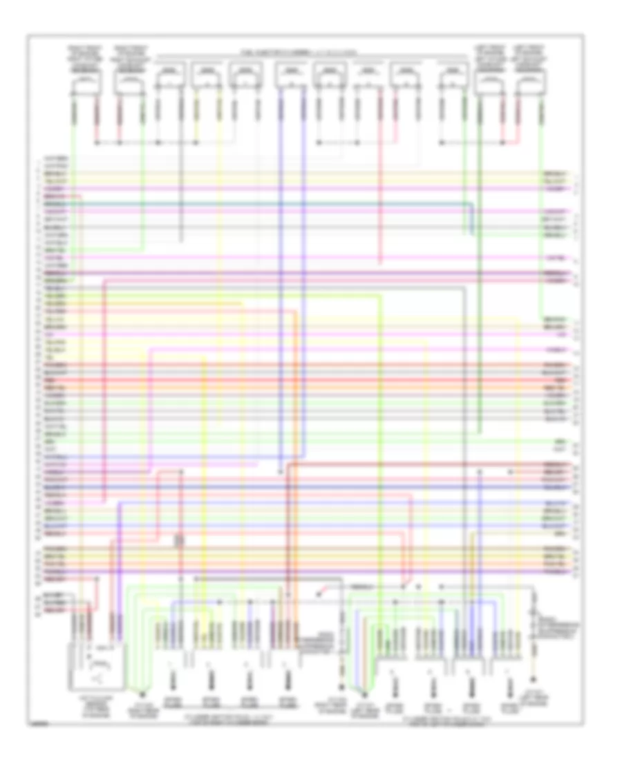
5.5L, Engine Performance Wiring Diagram (1 of 4) for Mercedes-Benz CLS550 2011

List of elements for 5.5L, Engine Performance Wiring Diagram (1 of 4) for Mercedes-Benz CLS550 2011:
- (top right side of fuel tank) fuel pump
- Agr_steller1
- A_p_zue1
- A_p_zue2
- A_p_zue3
- A_p_zue4
- A_p_zue5
- A_p_zue6
- A_p_zue7
- A_p_zue8
- A_s_dk
- A_s_hav
- A_s_slv
- A_t_dcm
- A_t_dcp
- A_t_kwths
- A_t_lsh1hk
- A_t_lsh2hk
- A_t_lshvk1
- A_t_lshvk2
- A_t_nwsa1
- A_t_nwse1
- A_t_nwse2
- A_t_su/suv
- A_u_5vg1m
- A_u_5vg2m
- A_u_lsu1vm
- A_u_lsu2vm
- A_u_uip
- Coolant temperature sensor (left rear of engine)
- Ev 1
- Ev 2
- Ev 3
- Ev 4
- Ev 5
- Ev 6
- Ev 7
- Ev 8
- E_a_ip2s
- E_a_ks1a
- E_a_ks2a
- E_a_ls2hk
- E_a_lshk
- E_a_lsu1ia
- E_a_lsu1un
- E_a_lsu2ia
- E_a_lsu2ip
- E_a_lsu2un
- E_a_tmot1
- E_f_kwgb
- E_f_nwga1
- E_f_nwga2
- E_f_nwge1
- E_f_nwge2
- Fuel pump relay module
- Fuse 20a
- Hot at all times
- Left exhaust camshaft hall sensor (left front of engine)
- Left intake camshaft hall sensor (left front of engine)
- Left intake manifold tumble flap position sensor (top left rear of engine)
- Lin
- Me-sfi (me) control unit (right rear of engine compt)
- M_r_hfm1
- M_r_ipm
- M_r_lsik
- M_r_senm1
- M_r_senm2
- Nca
- Nw_g_a2
- Pressure sensor (front of right cylinder bank)
- Rear sam control module w/ fuse & relay module (left side of trunk)
- Red
- Right exhaust camshaft hall sensor (right front of engine)
- Right intake camshaft hall sensor (right front of engine)
- Right intake manifold tumble flap position sensor (top right rear of engine)
- Sig
- Starting/charging system
- W6 (left side of trunk)
- X36/3
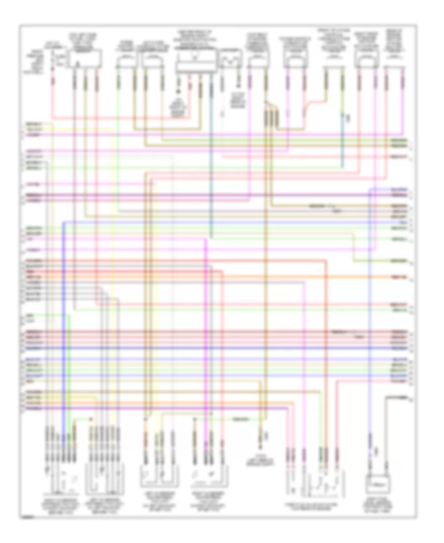
5.5L, Engine Performance Wiring Diagram (2 of 4) for Mercedes-Benz CLS550 2011
List of elements for 5.5L, Engine Performance Wiring Diagram (2 of 4) for Mercedes-Benz CLS550 2011:
- (left front of engine) left exhaust camshaft solenoid
- (left front of engine) left intake camshaft solenoid
- (right front of engine) right exhaust camshaft solenoid
- (right front of engine) right intake camshaft solenoid
- Cylinder ignition coils 1, 2, 3 & 4 (top of right cylinder bank)
- Cylinder ignition coils 5, 6, 7 & 8 (top of left cylinder bank)
- Fuel injector cylinders 1, 4, 7, 6, 2, 3, 8 & 5
- Hot film maf sensor (top rear of engine)
- Nca
- Radio interference suppression capacitor 1
- Radio interference suppression capacitor 2
- Red
- Spark plugs
- W11w1 (left rear of engine)
- W11w2 (right rear of engine)
5.5L, Engine Performance Wiring Diagram (3 of 4) for Mercedes-Benz CLS550 2011
List of elements for 5.5L, Engine Performance Wiring Diagram (3 of 4) for Mercedes-Benz CLS550 2011:
- (center front of engine compt) electric suction fan engine & ac w/ integrated control
- (front of intake manifold) variable intake manifold switchover valve
- (rear of engine) heating system shutoff valve
- (right front of engine) air pump switchover valve
- (top front of engine) three-disc thermostat valve
- (top left side of fuel tank) fuel tank pressure sensor
- Activated charcoal filter shutoff valve
- Air pump
- Front prefuse box (right front footwell)
- Fuse 100a
- Hot at all times
- Intake manifold tumble flap switchover valve
- Left o2 sensor downstream twc (kat) (in left exhaust, after twc)
- Left o2 sensor upstream twc (kat) (in left exhaust, before twc)
- Nca
- Purge control valve
- Red
- Right fuel level sensor (top right side of fuel tank)
- Right o2 sensor downstream twc (kat) (in right exhaust, after twc)
- Right o2 sensor upstream twc (kat) (in right exhaust, before twc)
- Sig
- Throttle valve actuator (top rear of engine)
- W11w2 (right rear of engine)
- W15/3 (left rear of engine compt)
- W2 (right front of engine compt)
- X205
- X26/1
- X26/2
- X36/3
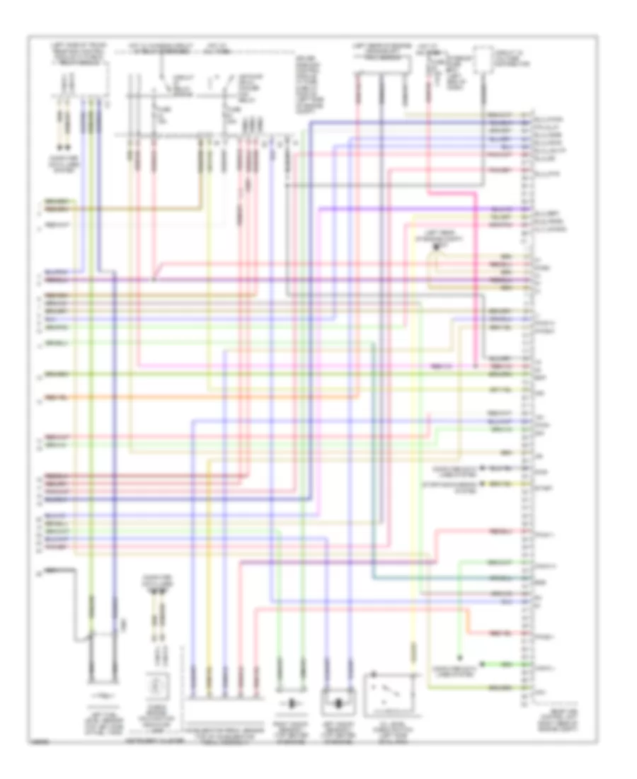
5.5L, Engine Performance Wiring Diagram (4 of 4) for Mercedes-Benz CLS550 2011
List of elements for 5.5L, Engine Performance Wiring Diagram (4 of 4) for Mercedes-Benz CLS550 2011:
- "check engine" malfunction indicator lamp
- (-)
- (left rear of engine compt) w15/3
- (left rear of engine) crankshaft hall sensor
- (left side of trunk) rear sam control module w/ fuse & relay module
- +5v
- 87me1
- 87me2
- 87me3
- Aav
- Accelerator pedal sensor (top of accelerator pedal assembly)
- Air
- Air pump or oil cooler fan relay
- A_t_nwsa2
- C42
- Can-b h
- Can-b l
- Can-c h
- Can-c l
- Circuit 15 voltage distributor
- Circuit relay engine
- Computer data lines system
- Diag
- Driver side sam control module w/ fuse & relay module (left side of engine compt)
- Egs
- Ekp
- E_a_ds
- E_a_ip1s
- E_a_ks1b
- E_a_ks2b
- E_a_lsu1ip
- E_f_kwga
- E_f_ref1
- E_s_fsoel
- Fuse 15a
- Fuse 40a
- Fuse 7.5a
- Hot at all times
- Hot w/ chassis circuit 87 relay energized
- Instrument cluster
- Interior fuse box (left end of dash)
- Left fuel level sensor (top left side of fuel tank)
- Left knock sensor 2 (top center of engine)
- Me-sfi (me) control unit (right rear of engine compt)
- Nca
- Nw_g_a1
- Oil level check switch (left side of oil pan)
- Pwg+
- Pwg1-0
- Pwg1-1
- Pwg2-0
- Pwg2-1
- Right knock sensor 1 (top center of engine)
- Sig
- Start
- Starting/charging system
- X26/1
- X36/3