ENGINE PERFORMANCE
3.5L
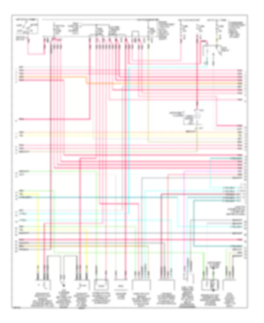
3.5L, Engine Performance Wiring Diagram (1 of 4) for Hyundai XG350 L 2004
 https://portal-diagnostov.com/license.html
Automotive Electricians Portal FZCO
Automotive Electricians Portal FZCO
https://portal-diagnostov.com/license.html
https://portal-diagnostov.com/license.html
Automotive Electricians Portal FZCO
Automotive Electricians Portal FZCO
List of elements for 3.5L, Engine Performance Wiring Diagram (1 of 4) for Hyundai XG350 L 2004:
- (top of engine)
- (top of engine) injectors
- (under center console, right of srs control module) g13
- A/c press sw
- A/c rly ctrl
- A/t fuse 20a
- A/t rly ctrl
- Afs sig
- Air conditioning system
- Aps source
- Ats sig
- B10
- C11
- C44-1
- C44-2
- Ccv sig
- Check eng ind
- Ckp sens sig
- Close sens
- Close(var int)
- Cmp sens sig
- Com area net
- Cruise control system
- Cruise control system cooling fans system
- Cruise ind
- Cruise sw ind
- Ecm fuse 10a
- Egr sol vlv
- Egr solenoid (on top right side of engine, on intake manifold)
- Electronic power steering system
- Engine comp- artment junction block (on left front of engine compt)
- Engine control relay (behind center of dash, on center support bracket)
- Eps
- Etc sens sig
- Ets rly ctrl
- F10
- F11
- Fan rly (hi)
- Fan rly (lo)
- Fuel pmp ctrl
- Fuel sender
- Fuel sender & fuel pump motor (beneath center of rear seat, in fuel tank)
- G07 (at left floorpanel crossmember)
- G08 (on left side of package shelf)
- G11 (on firewall, near throttle housing)
- G13 (under center console, right of srs control module)
- G14 (under center console, at right rear of srs control module)
- Gnd
- Hot at all times
- Ign coil 1
- Ign coil 2
- Ign coil 3
- Ign detect sig
- Ignition coil 1
- Ignition coil 2
- Ignition coil 3
- Ignition failure sensor (on upper left front of engine)
- Inj 1 ctrl
- Inj 2 ctrl
- Inj 3 ctrl
- Inj 4 ctrl
- Inj 5 ctrl
- Inj 6 ctrl
- Injector fuse 10a
- Instrument cluster system
- Jc01
- Limp home valve (on right rear of engine, near throttle body)
- Limp home vlv
- Main fuse 30a
- Memory pwr
- Nca
- O2s (heat)
- O2s (heating)
- Open sens
- Open(var int)
- P/n in
- Pcm (behind lower center of dash)
- Pcs vlv ctrl
- Pnk
- Power steering pressure switch (on power steering right side of engine)
- Pwr steering
- Red
- Rly ctrl
- Sens gnd
- Spark tim adj
- Starting/ charging system
- Tan
- To egr fuse (diagram 2 of 4)
- To spark plugs
- Trip
- Variable intake motor
- W/ immobilizer
- W/o immobilizer
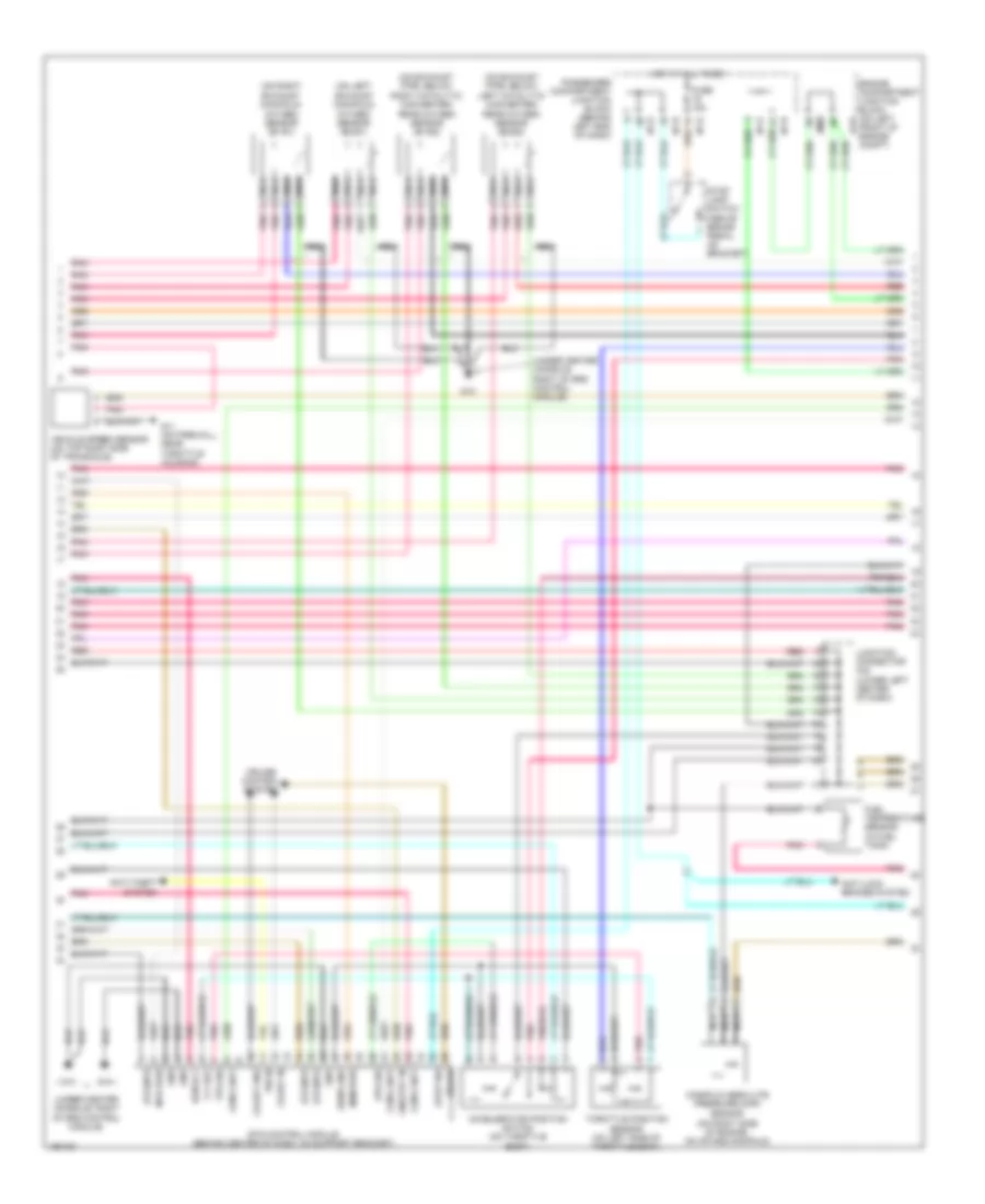
3.5L, Engine Performance Wiring Diagram (2 of 4) for Hyundai XG350 L 2004
List of elements for 3.5L, Engine Performance Wiring Diagram (2 of 4) for Hyundai XG350 L 2004:
- A11
- Abs fuse 10a
- Acc
- Camshaft position (cmp) sensor (on front of left cylinder head)
- Canister close valve
- Check engine ind (mil)
- Crankshaft position (ckp) sensor (on lower front of engine, behind crankshaft pulley)
- D10
- D11
- E10
- Egr fuse 15a
- Engine compartment junction block (on left front of engine compt)
- Engine coolant temperature sensor & sender (on rear of engine)
- Ets motor (on right side of throttle body)
- Ets relay
- From injector a fuse (diagram 1 of 4)
- Fuel tank pressure sensor (beneath left rear of vehicle, above suspension crossmember)
- Fuse 10a
- Fuse 15a
- G16 (in engine compt, between air cleaner & engine compt junction block)
- Hot at all times
- Hot in on or start
- I/p-b
- I/p-h
- I/p-j
- I18-1
- I18-2
- Ignition coil fuse 20a
- Ignition switch
- Instrument cluster
- Instrument cluster system
- Jc01
- Jm09
- Junction connector c41 (lower left center of dash)
- Lock off
- Mass air flow sensor (on left rear of engine compt, in air intake duct)
- Nca
- Oxygen sensor fuse 15a
- Passenger compartment junction block (behind left end of dash)
- Pnk
- Purge control solenoid valve (on rear of intake manifold, on bracket)
- Red
- Sender
- Sensor
- Start
- Variable intake sensor (on right rear of engine, on intake manifold)
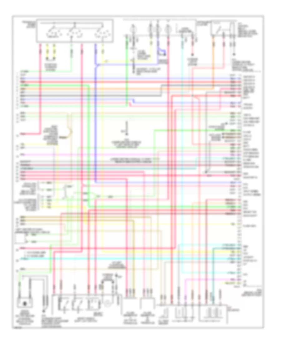
3.5L, Engine Performance Wiring Diagram (3 of 4) for Hyundai XG350 L 2004
List of elements for 3.5L, Engine Performance Wiring Diagram (3 of 4) for Hyundai XG350 L 2004:
- (on exhaust pipe, below left catalytic converter) rear oxygen sensor (b2/s2)
- (on exhaust pipe, below right catalytic converter) rear oxygen sensor (b1/s2)
- (on left exhaust manifold) oxygen sensor (b2/s1)
- (on right exhaust manifold) oxygen sensor (b1/s1)
- (under center console, right of srs control module)
- 5 v ref
- Accelerator position switch (on throttle body)
- Anti-lock brakes system
- Anti-theft system
- Aps sig
- Brake
- Coast gnd
- Coast in
- Com a net
- Cruise control system
- Ecm rly
- Engine compartment junction block (on left front of engine compt)
- Ets control module (behind center of dash, on support bracket)
- Ets mtr
- Fuel temperature sensor (in fuel tank)
- Fuse 15a
- G11 (on firewall, near throttle housing)
- G13
- G15
- Gnd
- Hot at all times
- I/p-e
- I/p-h
- I/p-k
- Jc01
- Jm09
- Junction connector c42 (lower left center of dash)
- Manifold absolute pressure (map)
- Mem pwr
- Mtr pwr
- Nca
- On/strt in
- P/n in
- Passenger compartment junction block (behind left end of dash)
- Pnk
- Red
- Sens gnd
- Sensor (on right side of engine, on intake manifold)
- Stop lamp switch (above brake pedal, on bracket)
- Stop sw
- Throttle position sensor (on left side of throttle body)
- Tps sig
- Vehicle speed sensor (on top right side of transaxle)
3.5L, Engine Performance Wiring Diagram (4 of 4) for Hyundai XG350 L 2004
List of elements for 3.5L, Engine Performance Wiring Diagram (4 of 4) for Hyundai XG350 L 2004:
- (at left floorpanel crossmember)
- (left center of dash) immobilizer control module
- (on right ``a" pillar near crash bar) g05
- (under center console, at right rear of srs control module)
- 2nd
- 5-in
- 5v ref
- A/c sig in
- A/t control relay (behind lower center of dash, behind pcm)
- A/t solenoid
- Air conditioning system
- Anti-lock brakes system
- Aps(main) sig
- Batt
- Body computer, electronic power steering & instrument cluster systems
- C44-3
- C44-4
- Can hi
- Can lo
- Com area net
- D-in
- Data link connector (dlc) (below left side of dash)
- Dcc
- Down shift
- Flash (eci)
- Ftp sens sig
- G07
- G14
- G14 (under center console, at right rear of srs control module)
- G15 (under center console, at left rear of srs control module)
- G16 (in engine compt between air cleaner & engine compt junction block)
- Gnd
- Ground
- I18-1
- I18-2
- I18-3
- Idle sw
- Input speed
- Instrument cluster
- Interior lights system
- J/c i28 (upper right side of dash)
- K-line
- Knock sens
- Knock sensor (on top center of engine, below intake manifold)
- Map sens sig
- Memory system
- Micro computer
- Multipurpose check connector (at lower left side of dash)
- N-in
- Nca
- Normal
- O/t
- O2s sig in
- O2s sig in fuel tem sens sig gnd
- Oil temp sensor
- On/start in
- Output speed
- P-in
- Pcm (behind lower center of dash)
- Pnk
- Pulse generator a (on top of transaxle)
- Pulse generator b (on transaxle)
- R-in
- Red
- Select
- Select sw
- Select switch
- Sens gnd
- Sport mode & shift limit switch
- Starting/ charging system
- Stop sw in
- Tps sig
- Transaxle range switch
- Up shift
- Vss in
- W/ immobilizer
- W/o immobilizer

 Čeština
 Dansk
Dansk Deutsch
 Ελληνικά
 English
 English
 Suomi
Suomi Français
 Français
 עברית
עברית Hrvatski
 Magyar
 Italiano
 日本語
日本語 한국어
한국어 Nederlands
 Polski
 Português
 Português
 Română
 Русский
 Slovenčina
 Slovenščina
 Svenska
 Türkçe
 中文 (中国)