SUPPLEMENTAL RESTRAINTS
Supplemental Restraint Wiring Diagram for Mercury Villager GS 1998
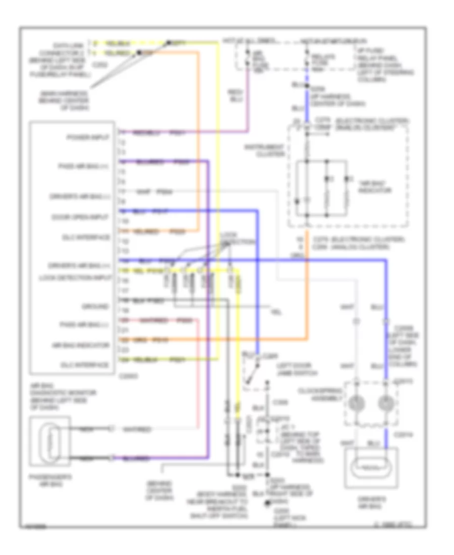
List of elements for Supplemental Restraint Wiring Diagram for Mercury Villager GS 1998:
- "air bag" indicator
- (behind center of dash)
- (main harness, behind center of dash)
- Air bag
- Air bag diagnostic monitor (behind left side of dash)
- Air bag fuse 10a
- Air bag indicator
- C 1995 vftc
- C2003
- C2008
- C2008 for
- C2010
- C2013
- C2014
- C2021
- C2021 for
- C2035 for
- C266
- C268
- C276 (electronic cluster) (analog cluster)
- C306
- Clockspring assembly
- Cluster
- Data link connector 2 (behind left side c252
- Dlc interface
- Door open input
- Driver's air bag
- Driver's air bag (+)
- Driver's air bag (-)
- For c2003
- Fuse/relay panel)
- G200 (left kick panel)
- Ground
- Hot at all times
- Hot in start or run
- I/p fuse/ relay panel (behind dash, left of steering column)
- Instrument
- J/c 1 (behind top left side of dash, taped
- Left door jamb switch
- Lock detection
- Lock detection input
- Nca
- Of dash, in i/p
- Pass air bag (+)
- Pass air bag (-)
- Passenger's
- Power input
- Ps01
- Ps03
- Ps04
- Ps05
- Ps06
- Ps15
- Ps17
- Ps18
- Ps20
- Ps21
- Pse2
- Relays fuse 10a
- S202 (body harness, near breakout to inertia fuel shut-off switch)
- S203 (i/p harness, right side of dash)
- S258 (i/p harness, center of dash)
- S271
- To main harness)
 Čeština
 Dansk
Dansk Deutsch
 Ελληνικά
 English
 English
 Suomi
Suomi Français
 Français
 עברית
עברית Hrvatski
 Magyar
 Italiano
 日本語
日本語 한국어
한국어 Nederlands
 Polski
 Português
 Português
 Română
 Русский
 Slovenčina
 Slovenščina
 Svenska
 Türkçe
 中文 (中国)
 Español