TRANSMISSION
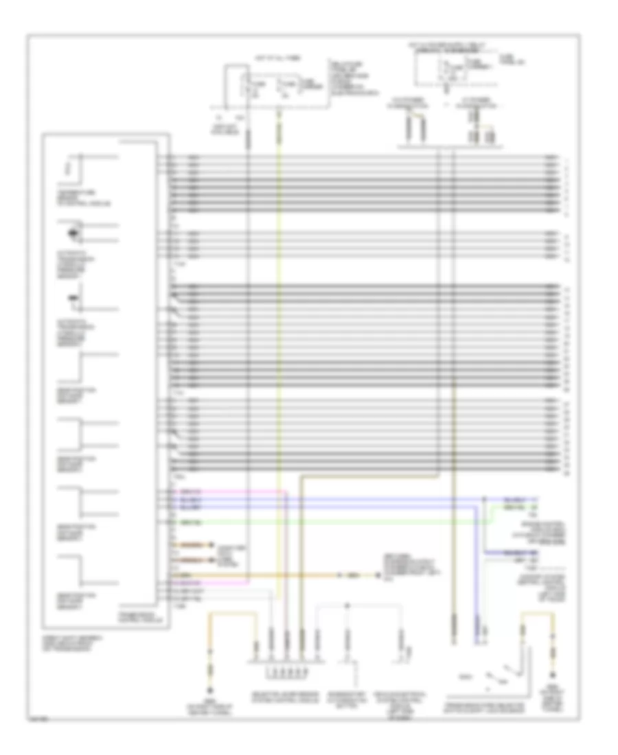
A/T Wiring Diagram, with Direct Shift (1 of 2) for Audi Q5 2010
List of elements for A/T Wiring Diagram, with Direct Shift (1 of 2) for Audi Q5 2010:
- (between suspension strut chamber & plenum chamber front left) g12
- (info not available)
- 10a
- 12a
- Access/start authorization button
- Automatic transmission hydraulic pressure sensor 1
- Automatic transmission hydraulic pressure sensor 2
- Comfort system central control module (left side of trunk)
- Computer data lines system
- Direct shift gearbox (dsg) mechatronic (on transmission)
- Engine control module (ecm) (in plenum chamber driver's side)
- Fuse 5a
- Fuse carrier
- Fuse carrier 1
- Fuse panel sc
- G688 (on right side of center tunnel)
- Gear position distance sensor 1
- Gear position distance sensor 2
- Gear position distance sensor 3
- Gear position distance sensor 4
- Hot at all times
- Nca
- Relay/fuse panel sb (driver's side plenum chamber on electronics box)
- Selector lever sensor system control module
- T14h
- T14i
- T16r
- T32b
- T32d
- T8al
- T94
- Temperature sensor (in control module)
- Transmission control module
- Transmission park selector switch & shift lock solenoid
- Vehicle electrical system control module (left side of dash)
- W/ phased in modification
- W/o phased in modification
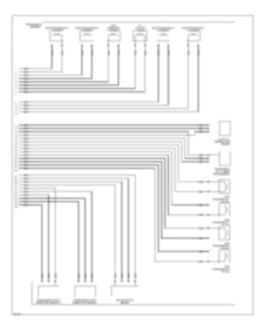
A/T Wiring Diagram, with Direct Shift (2 of 2) for Audi Q5 2010
List of elements for A/T Wiring Diagram, with Direct Shift (2 of 2) for Audi Q5 2010:
- Clutch oil temperature sensor
- Drive position sensor
- Main pressure valve
- Nca
- Oil cooling valve
- Sub- transmission 1 valve 1
- Sub- transmission 1 valve 2
- Sub- transmission 2 valve 1
- Sub- transmission 2 valve 2
- Sub-transmission 1 valve 3
- Sub-transmission 1 valve 4
- Sub-transmission 2 valve 3
- Sub-transmission 2 valve 4
- Transmission assembly
- Transmission input speed (rpm) sensor 1
- Transmission input speed (rpm) sensor 2
- Transmission input speed (rpm) sensor 3
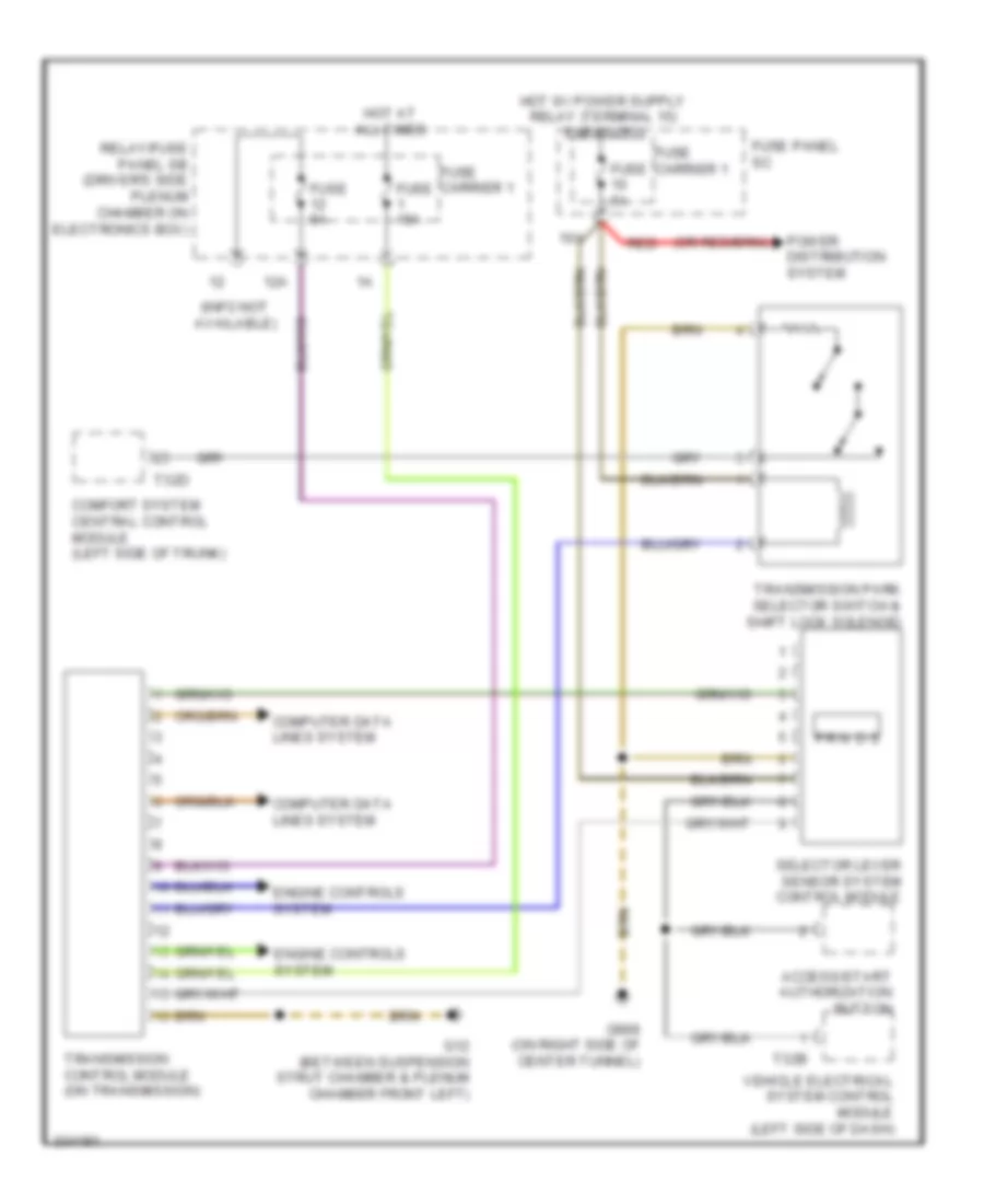
A/T Wiring Diagram, without Direct Shift for Audi Q5 2010
List of elements for A/T Wiring Diagram, without Direct Shift for Audi Q5 2010:
- (info not available)
- 10a
- 12a
- Access/start authorization button
- Comfort system central control module (left side of trunk)
- Computer data lines system
- Engine controls system
- Fuse 15a
- Fuse 5a
- Fuse carrier 1
- Fuse panel sc
- G12 (between suspension strut chamber & plenum chamber front left)
- G688 (on right side of center tunnel)
- Hot at all times
- N d s
- P r
- Power distribution system
- Red
- Relay/fuse panel sb (driver's side plenum chamber on electronics box)
- Selector lever sensor system control module
- T32b
- T32d
- Transmission control module (on transmission)
- Transmission park selector switch & shift lock solenoid
- Vehicle electrical system control module (left side of dash)
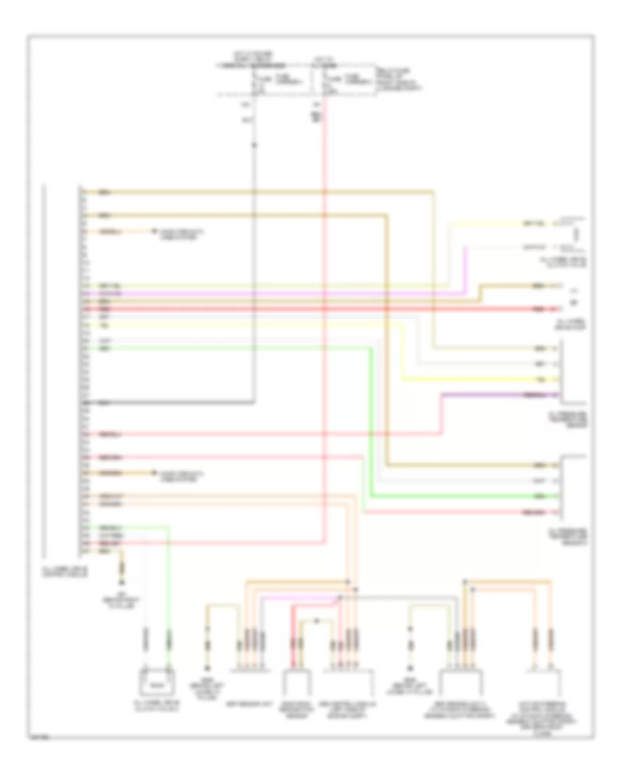
AWD Wiring Diagram for Audi Q5 2010
List of elements for AWD Wiring Diagram for Audi Q5 2010:
- 12a
- Abs control module (left side of engine compt)
- Active steering control module (w/ dynamic steering/ gearbox quattro sport) (driver's front floor)
- All wheel drive clutch valve
- All wheel drive clutch valve 2
- All wheel drive control module
- All wheel drive pump
- Computer data lines system
- Esp sensor unit
- Esp sensor unit 2 (w/ dynamic steering/ gearbox quattro sport)
- Fuse 35a
- Fuse 5a
- Fuse carrier 2
- Fuse carrier 4
- G51 (behind right "d" pillar)
- G639 (behind left lower "a" pillar)
- Hot at all times
- Oil pressure/ temperature sensor
- Oil pressure/ temperature sensor 2
- Red
- Relay/fuse panel sf (right side of luggage compt)
- Roof rack recognition sensor

 Čeština
 Dansk
Dansk Deutsch
 Ελληνικά
 English
 English
 Español
 Français
 Français
 עברית
עברית Hrvatski
 Magyar
 Italiano
 日本語
日本語 한국어
한국어 Nederlands
 Polski
 Português
 Português
 Română
 Русский
 Slovenčina
 Slovenščina
 Svenska
 Türkçe
 中文 (中国)