AIR CONDITIONING
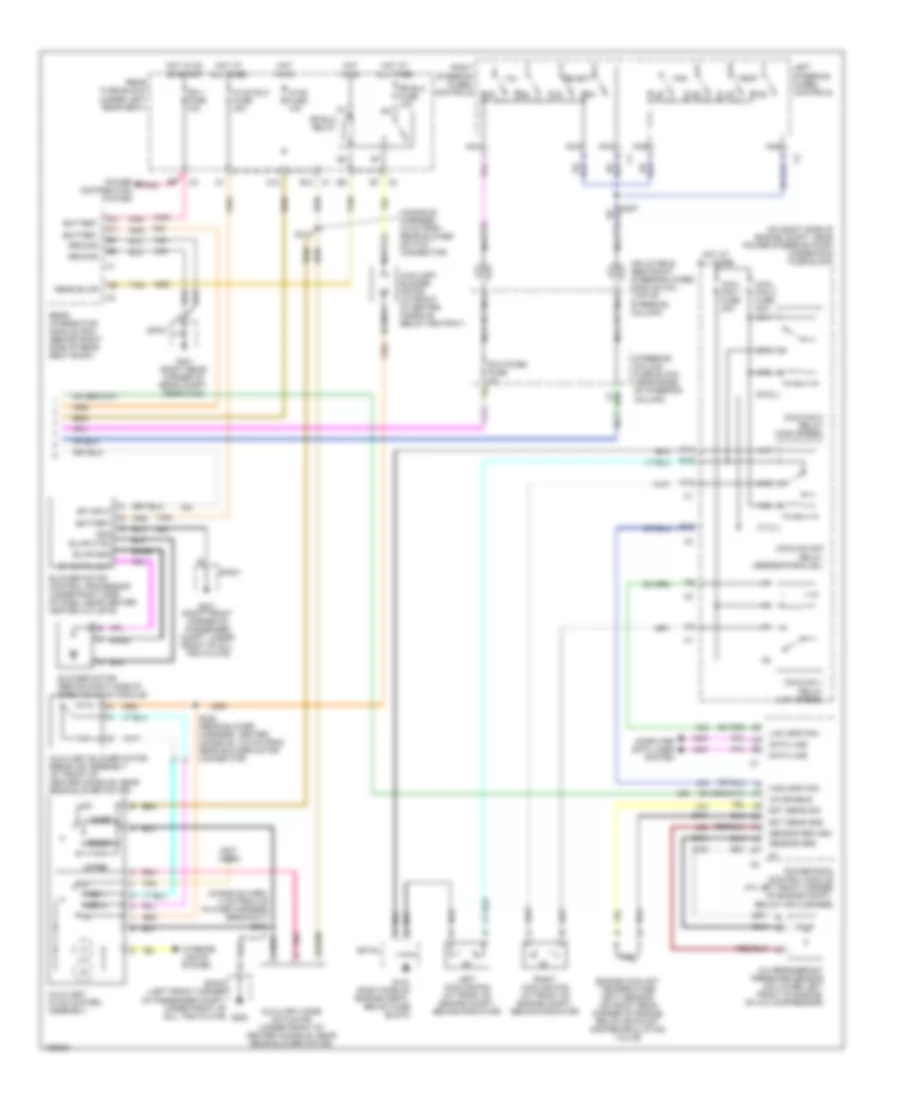
Automatic A/C Wiring Diagram (1 of 2) for Cadillac Seville SLS 2004
 https://portal-diagnostov.com/license.html
Automotive Electricians Portal FZCO
Automotive Electricians Portal FZCO
https://portal-diagnostov.com/license.html
https://portal-diagnostov.com/license.html
Automotive Electricians Portal FZCO
Automotive Electricians Portal FZCO
List of elements for Automatic A/C Wiring Diagram (1 of 2) for Cadillac Seville SLS 2004:
- & transmission breakout)
- (hvac harness, 73 cm from air inlet actuator)
- (hvac harness, 79.5 cm from air inlet actuator)
- (hvac harness, 89.5 cm from air inlet actuator)
- (i/p harness, 4 cm from left solar sensor harness breakout)
- (i/p harness, 8 cm from instrument cluster harness breakout)
- (lower left rear corner of
- 5v ref
- 5v vlv signal
- A/c clu fuse 15a
- A/c clu relay
- A/c compressor clutch
- A/c compressor clutch solenoid
- A/c compressor temperature switch
- A/c refrigerant low temperature sensor (at rear of engine compt, on a/c low side line)
- A10
- A11
- A12
- Acc
- Air temp vlv fd
- Air temp vlv sig
- Air temperature actuator (left) (behind left side of dash, on hvac module)
- Air temperature actuator (right) (behind right side of dash, on hvac module)
- Air temperature sensor (lower right) (below right side of dash, in a/c duct) air temperature sensor (lower left) (below left side of dash, in a/c duct)
- Air temperature sensor (upper right) (below right side of dash, in a/c duct) air temperature sensor (upper left) (below left side of dash, in a/c duct)
- Ambient air temperature sensor (on center front of vehicle, near hood latch)
- B12
- Battery
- C11
- Computer data lines system
- D11 blwr sp cntrl
- D16
- Dash integration module (dim) (on right side of dash, near blower motor)
- Data line
- Dim fuse 10a
- G201 (right front corner of passenger compt, under front of sill trim plate)
- Ground
- Headlights system
- Hot at all times
- Hot in on
- Hot in on or start
- I/p fuse 10a
- Ign 3 rr fuse 10a
- Ign sw fuse 15a
- Ignition
- Ignition switch
- Inside air temperature sensor (behind left side of dash, left of steering column)
- Inside air, 5v
- Instrument panel integration module (behind center of dash, above radio)
- L sunload, 5v
- Ll air temp, 5v
- Lock
- Lock run
- Lr air temp. 5v
- Mode actuator (behind left side of dash, on hvac module)
- Mode drive fd
- Motor return
- Nca
- Off
- Outside air, 5v
- Pnk
- Power distribution system
- R sunload, 5v
- Rear fuse block (under left rear seat)
- Recirc vlv fd
- Recirc vlv sig
- Recirculation actuator (behind right side of dash, on hvac module)
- Run
- S203 (i/p harness, 55.5 cm from radio connector)
- S204 (i/p harness, 64.5 cm from radio connector)
- S206
- S209
- S210 (i/p harness, 22 cm from left solar sensor harness breakout)
- S274
- S275
- S278
- Sensor grd
- Solid state
- Sp201
- Start
- Steer whl feed
- Steer whl rtn
- Sunload sensor (left) (on left side of dash, in defrost grille)
- Sunload sensor (right) (on right side of dash, in defrost grille)
- T10
- T11
- Tan
- Ul air temp, 5v
- Underhood fuse block (on right side of engine compt, near power steering pump)
- Ur air temp, 5v
- V10
- V11
Automatic A/C Wiring Diagram (2 of 2) for Cadillac Seville SLS 2004
List of elements for Automatic A/C Wiring Diagram (2 of 2) for Cadillac Seville SLS 2004:
- (console harn, 4 cm from cd player harness breakout) s318
- (console harness, 33 cm from rear blower switch connector)
- (not used)
- (on right side of engine compt, near power steering pump) underhood fuse block
- A/c enable
- A/c refrigerant pressure sensor (on lower left front of engine, on a/c compressor)
- A10
- A11
- Auxiliary blower motor (at front of center console, below ashtray)
- Auxiliary blower motor resistor assembly (at front of center console, near rear blower motor)
- Auxiliary hvac control assembly
- Auxiliary mode actuator (under front of center console, near rear blower motor)
- B10
- Bare
- Battery
- Blend
- Blower motor (behind right side of dash, on hvac module)
- Blower motor control processor (under right side of dash, near center heater outlets)
- Blwr ctrl
- Blwr gnd
- C10
- C11
- Computer data lines system
- Cool fan 1 fuse 30a
- Cool fan 2 fuse 30a
- Coolfan 1 relay (low speed)
- Coolfan 2 relay (high speed)
- Coolfan s/p relay (series/parallel)
- D10
- Data line
- E nca
- E10
- E11
- Ect sens gnd
- Ect sens sig
- Engine coolant temperature (ect) sensor (on right rear corner of engine, below exhaust gas recirculation valve)
- F11
- Fan
- G nca
- G10
- G104 (right side of engine compt, below fuse block)
- G11
- G200
- G201 (right front corner of passenger compt, under front of sill trim plate)
- G401 (right rear corner of rear compt, near c403)
- Gnd
- Ground
- High spd fan
- Hot at all times
- Hot in on
- Hot in on or start
- Hvac blo fuse 30a
- Hvac fuse 10a
- Ign 1 fuse 10a
- Inflatable restraint steering wheel module coil (top of steering column)
- Interior lights system
- Left cooling fan (at front of engine compt, behind radiator)
- Left steering wheel controls
- Low spd fan
- Lower
- Med 1
- Med 2
- Nca
- Off
- Pnk
- Power distribution system
- Powertrain control module (at left front corner of engine compt, below air cleaner)
- Rear blwr
- Rear fuse block (under left rear seat)
- Rear integration module (rim) (behind right side of rear seat back)
- Right cooling fan (at front of engine compt, behind radiator)
- Right steering wheel controls
- Rr blo fuse 10a
- Rr blo relay
- S227
- S317
- S322 (rear blower harness, center console, 12.5 cm from rear blower motor connector)
- Select
- Sensor grd
- Sensor return
- Sp cntrl out
- Sp input
- Sp104
- Sp200 (left front corner of passenger compt, under front of sill trim plate)
- Sp201
- Sp401
- Steering column fuse block (near base of steering column)
- Switches fuse 2a
- Tan
- Temp
- Upper
- Vol
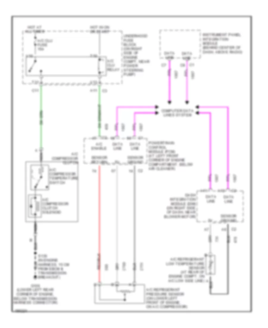
Compressor Wiring Diagram for Cadillac Seville SLS 2004
List of elements for Compressor Wiring Diagram for Cadillac Seville SLS 2004:
- A nca
- A/c clu fuse 15a
- A/c clu relay
- A/c compressor clutch
- A/c compressor clutch solenoid
- A/c compressor temperature switch
- A/c enable
- A/c refrigerant pressure sensor (on lower left front of engine, on a/c compressor)
- A11
- A12
- C1 c8
- C11
- Computer data lines system
- Dash integration module (dim) (on right side of dash, near blower motor)
- Data line
- G106 (lower left rear corner of engine, below transmission harness connector)
- Hot at all times
- Hot in on or start
- Instrument panel integration module (behind center of dash, above radio)
- Nca
- Powertrain control module (pcm) (at left front corner of engine compartment, below air cleaner)
- S130 (in engine harness, 15 cm from ebcm & transmission breakout)
- Sensor ground
- Sensor return
- T10
- T11
- Underhood fuse block (on right side of engine compt, near power steering pump)
- V10
- V11

 Čeština
 Dansk
Dansk Deutsch
 Ελληνικά
 English
 English
 Español
 Suomi
Suomi Français
 עברית
עברית Hrvatski
 Magyar
 Italiano
 日本語
日本語 한국어
한국어 Nederlands
 Polski
 Português
 Português
 Română
 Русский
 Slovenčina
 Slovenščina
 Svenska
 Türkçe
 中文 (中国)