AIR CONDITIONING
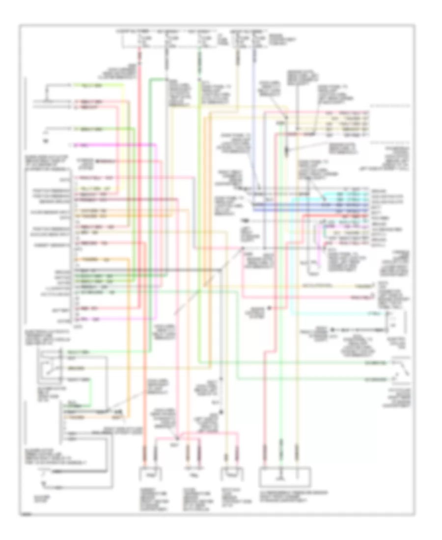
Air Conditioning Wiring Diagrams for Lincoln Mark VIII LSC 1997
List of elements for Air Conditioning Wiring Diagrams for Lincoln Mark VIII LSC 1997:
- (dash panel to headlamp junction harn, left rear corner of eng compt)
- (dash panel to headlamp junction harn, on elect cooling fan breakout)
- (dash panel to headlamp junction harn, on vlcm breakout)
- (dash panel to headlamp junction harn, right front corner of eng compt)
- (engine cntrl sens harn, in pcm breakout)
- (engine cntrl sens harn, left rear corner of eng compt)
- (left front of engine compt)
- (lower front center of eng compartment)
- (main harn, near air bag diagnostic module breakout)
- (main harn, near right i/p lamp breakout)
- (main harn, near tilt relay conn breakout)
- (right front corner of engine compartment) g101
- (right front corner of engine compt)
- (right side of floor pan, front of right door)
- A/c clutch coil
- A/c cycling sw
- A/c cycling switch (right rear of engine compartment)
- A/c demand req
- A/c refrigerant pressure sensor (right front corner of engine compartment)
- Ambient sensor in
- Ambient temperature sensor (front center of engine compartment)
- Batt
- Battery
- Blend door actuator (behind right side of i/p, on center of
- Blower motor
- Blower motor relay (right side of i/p)
- Blower motor speed controller (behind right side of i/p,
- C272
- C273
- Cooling fan mtr
- Data
- Data (+)
- Data (-)
- Eatc sun load sensor (top right side of i/p)
- Electric cooling fan
- Electronic automatic temperature control (eatc) module (center of i/p)
- Engine compartment fuse box
- Engine controls system
- Evaporator assembly)
- Fuse 10a
- Fuse 15a
- Fuse 40a
- G100
- G101
- G200 (left side of floor pan, front of left door)
- G203
- Ground
- Hot at all times
- Hot in run
- I/p fuse panel
- Ignition
- Illumination
- In-car sensor input
- In-car temperature sensor (behind center of i/p, near eatc module)
- Interior lights system
- Link connector (left side of engine compart- ment top of wheel well)
- Motor
- Nca
- Part of evaporator assembly)
- Pcm feed
- Position feedback
- Powertrain control module (pcm) (behind left side of i/p, on left side of safety wall)
- Red
- S104
- S137
- S139
- S141 (dash panel to headlamp junction harn, left rear corner of eng compartment)
- S156
- S161
- S165
- S171 (dash panel to headlamp junction harn, in a/c cycling sw breakout)
- S172
- S2017 (main harn, behind left side of i/p)
- S2019 (engine cntrl sens harn, in pcm breakout)
- S2020
- S208
- S247
- S288 (main harn, near elect automatic temp cntrl module breakout)
- S292 (main harness, near instrument cluster breakout)
- S295
- S296
- Sensor ground
- Sunload sens input
- Variable load control module (vlcm)
 Čeština
 Dansk
Dansk Deutsch
 Ελληνικά
 English
 English
 Español
 Suomi
Suomi Français
 עברית
עברית Hrvatski
 Magyar
 Italiano
 日本語
日本語 한국어
한국어 Nederlands
 Polski
 Português
 Português
 Română
 Русский
 Slovenčina
 Slovenščina
 Svenska
 Türkçe
 中文 (中国)
 Français