TRANSMISSION
Transmission Wiring Diagram (1 of 2) for Hyundai Elantra Limited 2013
 https://portal-diagnostov.com/license.html
Automotive Electricians Portal FZCO
Automotive Electricians Portal FZCO
https://portal-diagnostov.com/license.html
https://portal-diagnostov.com/license.html
Automotive Electricians Portal FZCO
Automotive Electricians Portal FZCO
List of elements for Transmission Wiring Diagram (1 of 2) for Hyundai Elantra Limited 2013:
- (or red)
- (right center of dash)
- Atm lever indicator
- Atm solenoid valve (on top of transaxle)
- C-can hi
- C-can lo
- Cng-aa
- Cng-ab
- Computer data lines system
- D ind
- Down shift
- E/r-cngb
- Ec11
- Ecu 4 fuse 15a
- Em61
- Ems box
- Exterior lights system
- Gm02
- Gng02
- Ground
- Hot at all times
- Hot in on or start
- I/p-h
- Ill.
- In spd pwr
- In spd sig
- Input speed
- Interior lights system
- Memory pwr
- Module 4 fuse 7.5a
- N ind
- Oil temp snsr +
- Oil temp snsr -
- Out spd pwr
- Out spd sig
- Output speed
- P ind
- Pcm (left rear of engine compt)
- Pnk
- R ind
- Red
- Select sw
- Select switch
- Sensor temperature oil
- Smart junction box (under left side of dash, near kick panel)
- Sol pwr 1
- Sol pwr 2
- Sport mode switch
- Ss a
- Ss b
- Ss-a
- Up shift
- Vfs 26b
- Vfs 35r
- Vfs line
- Vfs od
- Vfs t/con
- Vfs ud
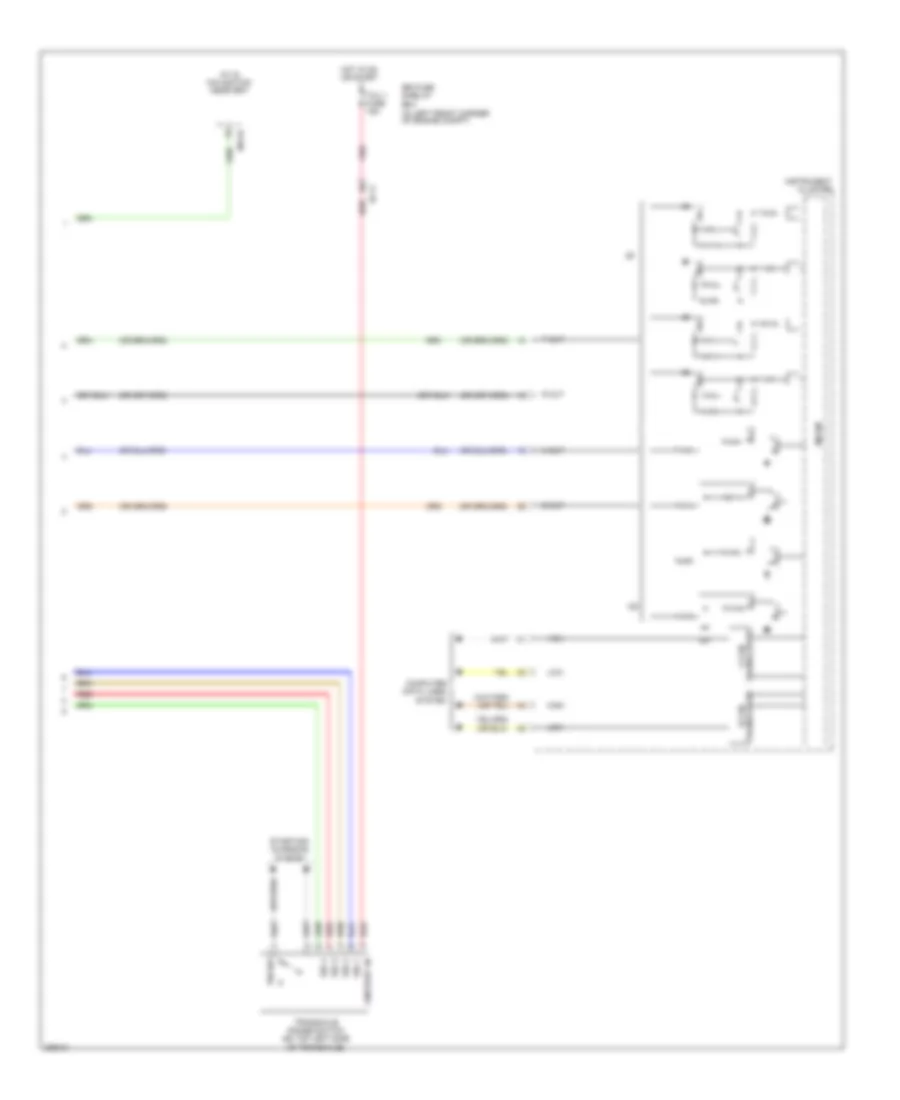
Transmission Wiring Diagram (2 of 2) for Hyundai Elantra Limited 2013
List of elements for Transmission Wiring Diagram (2 of 2) for Hyundai Elantra Limited 2013:
- (in left front corner of engine compt)
- A/v & navigation head unit
- B-can transceiver
- C-can transceiver
- Computer data lines system
- D out
- E/r fuse & relay box
- Ec11
- High
- Hot in on or start
- Ig+
- Instrument cluster
- Low
- M15-b
- Micom
- N out
- On/start in
- P out
- P/n sw
- Pnk
- R out
- Red
- Sig 1
- Sig 2
- Sig 3
- Sig 4
- Starting/ charging system
- Tcu 1 fuse 15a
- Transaxle range switch (on top left side of transaxle)


 Deutsch
 English
 English
 Español
 Nederlands
 Русский

