TRANSMISSION
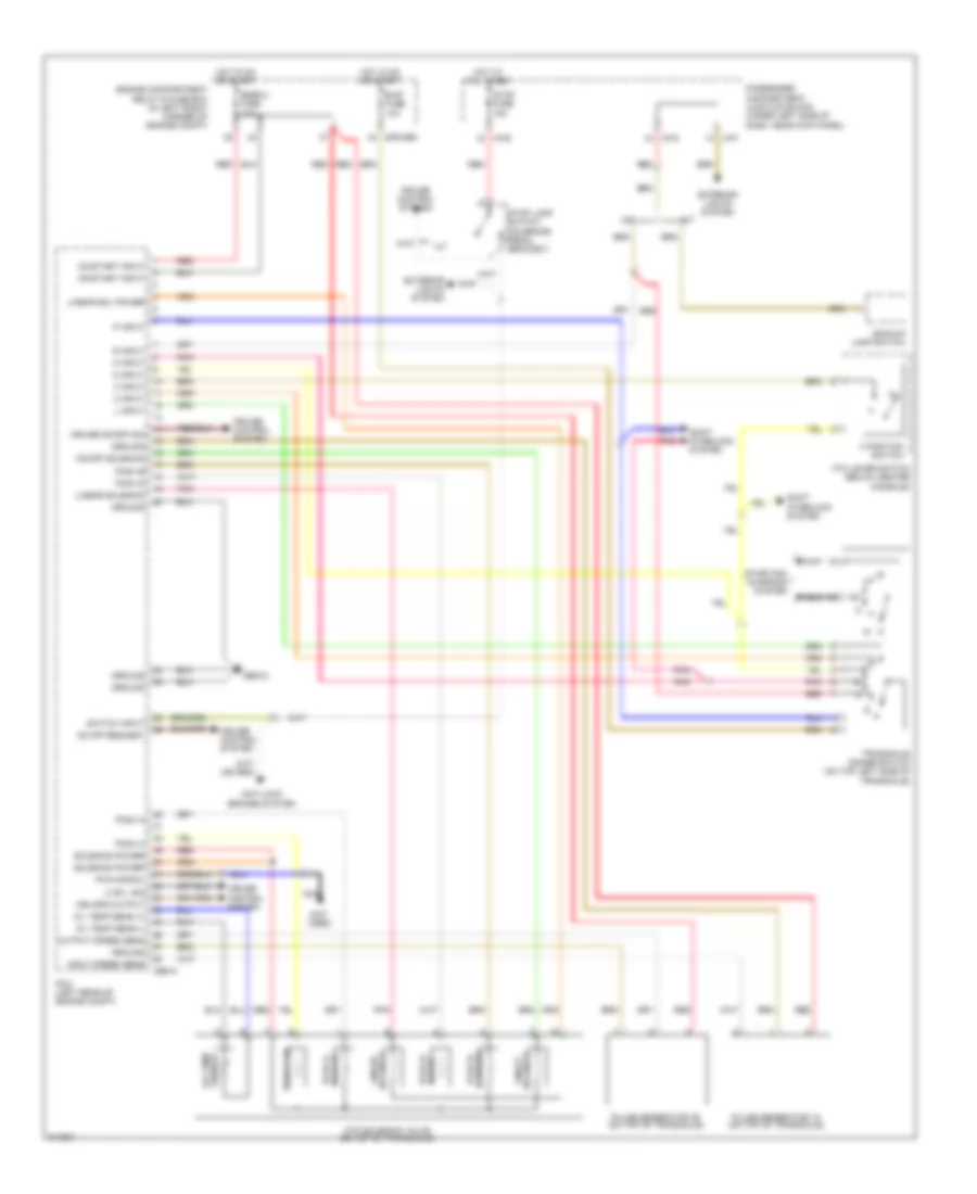
Transmission Wiring Diagram for Hyundai Elantra Touring GLS 2010
List of elements for Transmission Wiring Diagram for Hyundai Elantra Touring GLS 2010:
- (not used)
- 2 input
- 2 or l sig
- 3 input
- 3 position switch
- A/t
- Anti-lock brakes system
- Atm lever switch (below center console)
- Atm solenoid valve (on top of transaxle)
- B/up fuse 10a
- Backup lamp switch
- Cbg-a
- Cruise control system
- Cruise on/off sig
- D input
- E/r-cbg
- Engine compartment relay & fuse box (in left front corner of engine compt)
- Exterior lights system
- Gbg12
- Ground
- Hot at all times
- Hot in on or start
- I/p-b
- I/p-d
- I/p-f
- Input speed sens
- L input
- Linear sol power
- Linear solenoid
- M/t
- N input
- Nca
- Od & lr pcsv-a
- Od off request
- Oil temp sens (+)
- Oil temp sens (-)
- On/off solenoid
- On/start input
- Output speed sens
- P input
- Passenger compartment junction block (under left side of dash, near kick panel)
- Pcm (left rear of engine compt)
- Pcsv-a
- Pcsv-b
- Pcsv-b 24 brake
- Pcsv-c
- Pcsv-c ud
- Pcsv-d
- Pcsv-d dccsv
- Pnk
- Pulse generator "a" (on top of transaxle)
- Pulse generator "b" (on top of transaxle)
- Pwm signal
- R input
- Red
- Sensor oil temp
- Shift interlock system
- Snsr 2 fuse 10a
- Solenoid linear
- Solenoid power
- Starting/ charging system
- Stop fuse 15a
- Stop lamp switch (on brake pedal bracket)
- Switch input
- Transaxle range switch (on top left side of transaxle)
- Veh spd output
 Čeština
 Dansk
Dansk Deutsch
 Ελληνικά
 English
 English
 Español
 Suomi
Suomi Français
 עברית
עברית Hrvatski
 Magyar
 Italiano
 日本語
日本語 한국어
한국어 Nederlands
 Polski
 Português
 Português
 Română
 Русский
 Slovenčina
 Slovenščina
 Svenska
 Türkçe
 中文 (中国)
 Français