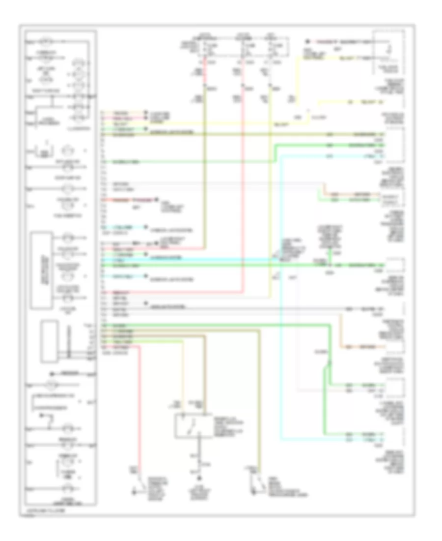
INSTRUMENT CLUSTER
Instrument Cluster Wiring Diagram for Ford Pickup F250 Super Duty 1999
List of elements for Instrument Cluster Wiring Diagram for Ford Pickup F250 Super Duty 1999:
- (conn a)
- (conn b)
- (lower right kick panel) g203
- (main harn, near breakout to instrument cluster) s232
- (under right side of dash) rear air suspension data link connector
- 4 wheel anti- lock brake system module (on left side of engine compt)
- 4x4 high ind
- 4x4 low ind
- 5.4l ngv
- 820 ohms
- A10
- A14
- A15
- A17
- A22
- Airbag ind
- Anti-lock ind
- B10
- B11
- B12
- B13
- B14
- B16
- B17
- B18
- B19
- B20
- Bias ckt
- Brake fluid level indicator switch (on brake fluid reservoir)
- Brake ind
- C146
- C2005
- C222
- C236
- C237
- C239
- C241
- C242
- C243
- C285
- C296
- Central junction box
- Charge ind
- Charging system
- Check suspension ind
- Computer data lines system
- Door ajar ind
- Engine oil pressure switch (on left front of engine)
- Exterior lights system
- Fasten safety belt ind
- Fuel pump assembly (under vehicle, at fuel tank)
- Fuel pump module
- Fuel reset ind
- Fuse 30a
- Fuse 5a
- G108 (left front radiator support)
- G200 (lower left kick panel)
- Gas
- Generic electronic module (behind left side of dash)
- Headlights system
- Hi beam ind
- Hot at all times
- Hot in run
- Hot in start or run
- Illumination
- Inertia fuel shutoff switch (under right side of dash)
- Instrument cluster
- Interior lights system
- Left turn ind
- Low fuel ind
- Low oil/high coolant ind
- Malfunction indicator
- Micro- processor
- Microprocessor
- Nca
- Ngv module (on front of engine)
- Park brake switch (on right side of parking brake lever)
- Passive anti-theft system transceiver module (behind left side of dash)
- Rear air suspension module (behind center of dash)
- Rear anti- lock brake system module (behind right side of dash)
- Restraints control module (behind right side of dash)
- Right turn ind
- Rx input
- S106
- S2002
- S204
- S207
- S265
- S289
- S294
- Theft indicator micro cluster
- Tx input
 Čeština
 Dansk
Dansk Deutsch
 Ελληνικά
 English
 English
 Español
 Suomi
Suomi Français
 עברית
עברית Hrvatski
 Magyar
 Italiano
 日本語
日本語 한국어
한국어 Nederlands
 Polski
 Português
 Português
 Română
 Русский
 Slovenčina
 Slovenščina
 Svenska
 Türkçe
 中文 (中国)
 Français