POWER DISTRIBUTION
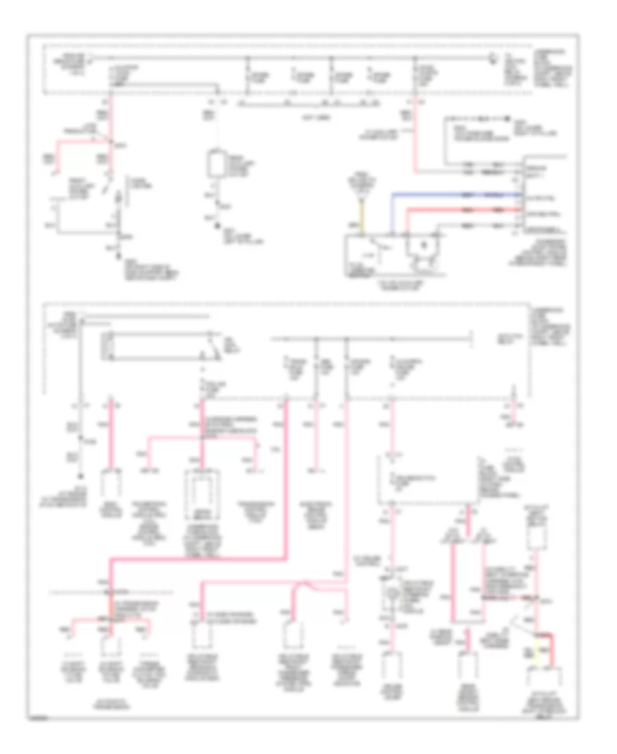
Power Distribution Wiring Diagram (1 of 4) for Chevrolet Uplander LT 2006
 https://portal-diagnostov.com/license.html
Automotive Electricians Portal FZCO
Automotive Electricians Portal FZCO
https://portal-diagnostov.com/license.html
https://portal-diagnostov.com/license.html
Automotive Electricians Portal FZCO
Automotive Electricians Portal FZCO
List of elements for Power Distribution Wiring Diagram (1 of 4) for Chevrolet Uplander LT 2006:
- (diagram 1 of 4)
- 12 volt reference
- 3.5l
- 3.9l
- A/c cltch fuse 10a
- A/c cltch relay
- Abs motor fuse 60a
- Acc
- Batt main 1 fuse 40a (early production, no information available)
- Batt main 2 fuse 60a
- Batt main 3 fuse 60a
- Battery
- Blower motor resistor assembly
- Body control module (bcm)
- Crank voltage
- Crnk relay
- Electronic brake control module (ebcm)
- Engine control module (ecm)
- Fan 1 fuse 30a
- Fan 1 relay
- Fan 2 fuse 40a
- Fan 2 relay
- Fan 3 relay
- From batt main 3 fuse b
- From horn fuse c
- Frt blwr hi fuse 40a
- Frt wiper fuse 25a
- Frt wsw fuse 15a
- Fuel pump fuse 15a
- Fuel pump relay
- Generator
- Hi beam relay
- Horn fuse 15a
- Horn relay
- Ignition switch
- Ignition voltage
- Ip fuse block (right side of dash, behind access panel)
- Lo beam relay
- Lock
- Pcm etc fuse 15a
- Pnk
- Powertrain control module (pcm)
- Pwr/trn relay
- Red
- Rr defog fuse 40a
- Rr defog relay 30
- Run
- Run rly relay
- S135 (in engine harness, 5 cm from breakout for starter motor)
- S139
- S159
- S160
- S279 (in steering column harness, 20 cm from c201)
- Start
- Starter motor
- Strtr sol fuse 40a
- To 115 vac auxiliary power outlet (diagram 2 of 4)
- To aux/pwr 12vdc fuse (diagram 2 of 4)
- To fan 1 fuse (diagram 1 of 4)
- To frt wsw fuse (diagram 1 of 4)
- To ip fuse block (diagram 3 of 4)
- To ip fuse block (diagram 4 of 4)
- Transmission control module (tcm)
- Underhood fuse block (in underhood compt, above right front wheel well)
- W/ auxiliary power outlet
- Wpr 1 relay
Power Distribution Wiring Diagram (2 of 4) for Chevrolet Uplander LT 2006
List of elements for Power Distribution Wiring Diagram (2 of 4) for Chevrolet Uplander LT 2006:
- (diagram 1 of 4)
- (in engine harness, 59 cm from engine fuse block) s175
- (in mobility seat base harness)
- (in mobility seat interface harness, 9 cm from breakout pnk for c206) s362
- (in transmission harness, 9.5 cm from c175) s171
- (not used)
- (w/ cruise control)
- (w/ side air bags)
- (w/o side air bags)
- 1-2 shift solenoid (1-2 ss) valve
- 115 vac auxiliary power outlet
- 2-3 shift solenoid (2-3 ss) valve
- 3.9l
- A10
- Abs fuse 10a
- Ac/cltch relay
- Ac/dc invrtr fuse 25a
- Accessory ac/dc power control module (behind right rear interior body panel)
- Air bag fuse 10a
- Apo neutral
- Apo phase a
- Automatic transmission
- Aux/pwr 12vdc fuse 25a
- Batt +
- Body control module
- C175
- C277
- C279
- Cigar lighter
- Crank relay
- Cruise control lever
- Cruise/switch fuse 2a
- Electronic brake control module (ebcm)
- From ac/dc e
- From rr defog fuse d
- From splice 273 (diagram 1 of 4)
- Front auxiliary power outlet
- G113 (at engine to transmission stud above g115)
- G200 (on right side of dash support beam, above dash compt)
- G301 (on lower left "b" pillar)
- G400 (on lower right "d" pillar)
- Ground
- Hvac control module
- Hvac/rpa/ cruise fuse 10a
- Ign main relay
- Inflatable restraint front passenger presence system (pps) module
- Inflatable restraint passenger airbag on/off indicator
- Inflatable restraint sensing & diagnostic module (sdm)
- Inflatable restraint steering wheel coil module
- Invtr ctrl
- Invtr fuse (diagram 2 of 4)
- Ip fuse block (right side of dash, behind access panel)
- Late production
- Nca
- Pcm ign fuse 10a
- Plug inserted switch
- Pnk
- Powertrain control module (pcm) (3.5l) engine control module (ecm) (3.9l)
- Rear auxiliary power outlet
- Rear object sensor control module
- Red
- S155
- S246
- S270
- S331
- S373
- S374
- S404 (w/o pass side power sliding door)
- Sit-n-lift seat/ ignition relay
- Sit-n-lift seat/brake transmission shift interlock relay
- Spare fuse
- To ignition main relay (diagram 2 or 4)
- Torque converter clutch (tcc) solenoid valve
- Trans sols fuse 10a
- Transmission control module (tcm)
- Underhood fuse block (in underhood compt, above right front wheel well)
- W/ auxiliary power outlet
- W/ rear parking assist
- W/ sit-n- lift seat
- W/o sit-n- lift seat
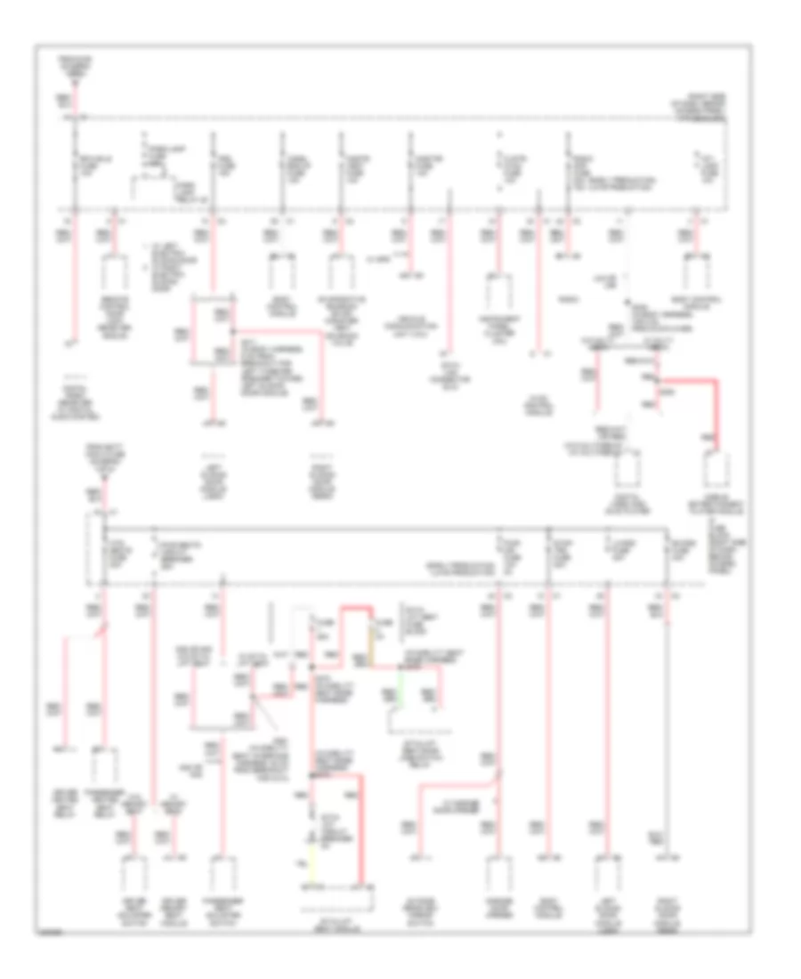
Power Distribution Wiring Diagram (3 of 4) for Chevrolet Uplander LT 2006
List of elements for Power Distribution Wiring Diagram (3 of 4) for Chevrolet Uplander LT 2006:
- (early production)
- (early production) (late production)
- (in mobility seat base harness) s372
- (in mobility seat base harness) s376
- (late production)
- (right side of dash, behind access panel) ip fuse block
- (w/o multimedia) (w/ multimedia)
- Ag2 or ah8
- Ag2 or ah8 w/o sit-n- lift seat
- Body control module
- Chmsl bck/up fuse 15a
- Clstr/ hvac fuse 10a
- Cnstr/ vent fuse 10a
- Data link connector (dlc)
- Digital radio receiver (w/ digital audio system)
- Digital video disc (dvd) player
- Driver heated seat relay
- Driver memory seat module
- Driver seat adjuster switch
- Electric sliding door
- Evaporative emission (evap) canister vent solenoid valve
- From batt main 2 fuse (diagram 1 of 4)
- From s160 (diagram 1 or 4)
- Fuse 25a
- Fuse 3a
- Garage door opener
- Htd/ seats fuse 20a
- Hvac control module
- Instrument panel cluster (ipc)
- Int/ lamp fuse 10a
- Ip fuse block (right side of dash, behind access panel)
- Left sliding door module (lsdm)
- Lh-psd fuse 40a
- Mobile entertainment player module
- Onstar fuse 10a
- Outside rearview mirror switch
- Park lamp relay 28
- Park/lamp fuse 10a
- Passenger heated seat relay
- Passenger seat adjuster switch
- Psd fuse 15a
- Pwr seats circuit breaker 25a
- Pwr/ mir fuse 10a 2a
- Radio
- Radio amp fuse 20a 15a
- Red
- Remote control door lock receiver (rcdlr)
- Rfa mdls fuse 10a
- Rh-psd fuse 40a
- Right sliding door module (rsdm)
- S339 (in body harness, 109.2 cm from dvd player)
- S361 (in mobility seat interface harness, 52 cm from breakout for c314)
- S370 (in mobility red
- S394
- S411 (in body harness, 6 cm from breakout for left tweeter speaker toward left sliding door module)
- Seat base harness)
- Sit-n- lift circuit breaker 8a
- Sit-n- lift seat fuse block
- Sit-n-lift seat module
- Sit-n-lift seat/door jamb switch relay
- Stop/ trn fuse 20a
- U42 or u56
- Vehicle communication unit (vcu)
- W/ garage door opener
- W/ gps
- W/ left electric sliding door w/ right
- W/ memory seat
- W/ multi- media
- W/ sit-n- lift seat
- W/o memory seat
- W/o multi- media
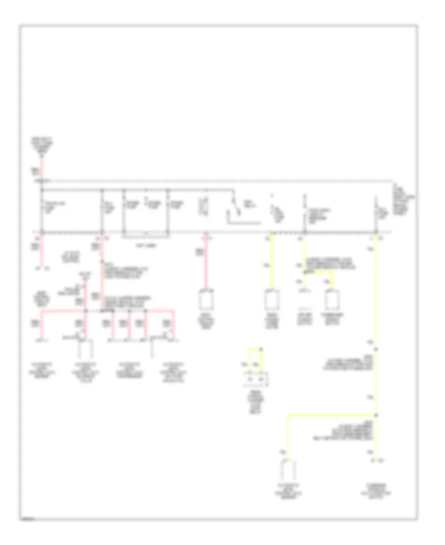
Power Distribution Wiring Diagram (4 of 4) for Chevrolet Uplander LT 2006
List of elements for Power Distribution Wiring Diagram (4 of 4) for Chevrolet Uplander LT 2006:
- (in alc jumper harness, inside vehicle, 16 cm from pass-through) s433
- (not used)
- Automatic level control (alc) compressor
- Automatic level control (alc) inflator air switch
- Automatic level control (alc) sensor
- Automatic level control (alc) solenoid valve
- Body control module (bcm)
- Driver window switch
- Elc fuse 20a
- Elc fuse 25a
- From batt main 3 fuse (diagram 1 of 4)
- Ip fuse block (right side of dash, behind access panel)
- Overhead console multi-function switch
- Passenger window switch
- Pwr wndw circuit breaker 25a
- Rap relay
- Rear window washer fluid pump relay
- Rear window wiper motor
- Rr wpr fuse 15a
- S204 (in dash harness, 10 cm from breakout for c204 toward dash fuse block)
- S300 (in body harness, 20 cm from breakout for passenger seat belt retractor toward c204)
- S415 (in body harness, 5 cm from breakout for c405 toward c479)
- Spare fuse
- Trunk/lks fuse 15a
- W/ auto air level control
- W/ inflator
- W/ trailer provisions

 Čeština
 Dansk
Dansk Deutsch
 Ελληνικά
 English
 English
 Español
 Suomi
Suomi Français
 עברית
עברית Hrvatski
 Magyar
 Italiano
 日本語
日本語 한국어
한국어 Nederlands
 Polski
 Português
 Português
 Română
 Русский
 Slovenčina
 Slovenščina
 Svenska
 Türkçe
 中文 (中国)