WARNING SYSTEMS
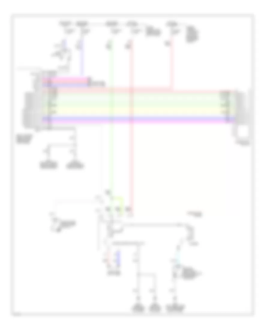
Warning Systems Wiring Diagram for Infiniti G35 2003
 https://portal-diagnostov.com/license.html
Automotive Electricians Portal FZCO
Automotive Electricians Portal FZCO
https://portal-diagnostov.com/license.html
https://portal-diagnostov.com/license.html
Automotive Electricians Portal FZCO
Automotive Electricians Portal FZCO
List of elements for Warning Systems Wiring Diagram for Infiniti G35 2003:
- 15a
- Bat
- Body control module (bcm) (behind left kick panel)
- Buzzer
- Can-h
- Can-l
- Comb sw in 1
- Comb sw in 2
- Comb sw in 3
- Comb sw in 4
- Comb sw in 5
- Comb sw out 1
- Comb sw out 2
- Comb sw out 3
- Comb sw out 4
- Comb sw out 5
- Combination meter
- Combination switch
- Computer data lines
- Door sw (dr)
- Driver seat belt buckle switch (inside belt buckle)
- Driver side front door switch
- E17 (on right side of engine compartment)
- E43 (on left front side of engine compartment)
- Fuse & fusible link block (at right rear side of engine compt)
- Fuse 1 10a
- Fuse 14 10a
- Fuse 19 10a
- Fuse 21 10a
- Fuse block (j/b) (behind left kick panel)
- Fuse f 50a
- Gnd
- Hot at all times
- Hot in acc or on
- Hot in on or start
- Ign
- Input 1
- Input 2
- Input 3
- Input 4
- Input 5
- K-line
- Key sw
- Key switch
- M30 (behind instrument cluster)
- M66 (behind right side of dash)
- M66 (left front side of passenger compt floor)
- Output 1
- Output 2
- Output 3
- Output 4
- Output 5
- Red
- Unified meter control unit
 Čeština
 Dansk
Dansk Deutsch
 Ελληνικά
 English
 English
 Español
 Suomi
Suomi Français
 Français
 Hrvatski
 Magyar
 Italiano
 日本語
日本語 한국어
한국어 Nederlands
 Polski
 Português
 Português
 Română
 Русский
 Slovenčina
 Slovenščina
 Svenska
 Türkçe
 中文 (中国)
 עברית
עברית
