ANTI-LOCK BRAKES
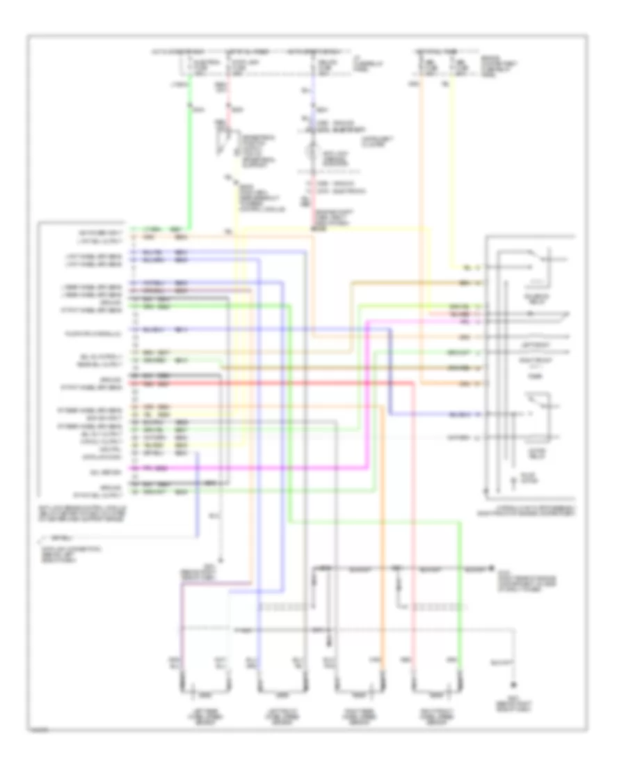
Anti-lock Brake Wiring Diagrams for Mercury Villager GS 1998
 https://portal-diagnostov.com/license.html
Automotive Electricians Portal FZCO
Automotive Electricians Portal FZCO
https://portal-diagnostov.com/license.html
https://portal-diagnostov.com/license.html
Automotive Electricians Portal FZCO
Automotive Electricians Portal FZCO
List of elements for Anti-lock Brake Wiring Diagrams for Mercury Villager GS 1998:
- (analog)
- (electronic)
- (engine compt harn, right side of dash) s286
- Abs fuse 20a
- Abs fuse 30a
- Anti-lock brake control module (below center of dash, mounted on center dash support brace)
- Anti-lock warning indicator
- Boo sw input
- Brake pedal position switch (top of brake pedal support)
- Bs01
- Bs02
- Bs04
- Bs05
- Bs08
- Bs09
- Bs14
- Bs17
- Bs18
- Bs21
- Bs23
- Bs24
- Bs25
- Bs26
- Bs27
- Bs28
- Bs29
- Bs30
- Bs32
- Bs35
- C268
- C276
- Data link conn
- Data link connector 2 (behind left side of dash)
- Eb10
- Eb20
- Eb34
- Electron fuse 10a
- Engine compartment fuse/relay panel
- G103 (right rear of engine compartment, on side of strut tower)
- G201 (behind right side of dash)
- Ground
- Hot at all times
- Hot in start or run
- Hydraulic actuator assembly (right front of engine compartment)
- I/p fuse/relay panel
- Ign power input
- Ind ctrl
- Instrument cluster
- L fnt sol output
- L fnt wheel spd sens
- L rear wheel spd sens
- Left front
- Left front wheel speed sensor
- Left rear wheel speed sensor
- Motor relay
- Mtr rly output
- Nca
- Pump motor
- Pump mtr (hydraulic)
- Rear
- Rear sol output
- Red
- Relays fuse 10a
- Right front
- Right front wheel speed sensor
- Right rear wheel speed sensor
- Rt fnt sol output
- Rt fnt wheel spd sens
- Rt rear wheel spd sens
- S2006 (main harn, near breakout to speed control module)
- S213
- S214
- S215
- S216
- S224
- S239
- S244
- Sol return
- Sol rly output
- Sol rly/mtr rly
- Solenoid relay
- Stop lamp fuse 15a
 Čeština
 Dansk
Dansk Deutsch
 Ελληνικά
 English
 English
 Español
 Suomi
Suomi Français
 Français
 Hrvatski
 Magyar
 Italiano
 日本語
日本語 한국어
한국어 Nederlands
 Polski
 Português
 Português
 Română
 Русский
 Slovenčina
 Slovenščina
 Svenska
 Türkçe
 中文 (中国)
 עברית
עברית
