HORN
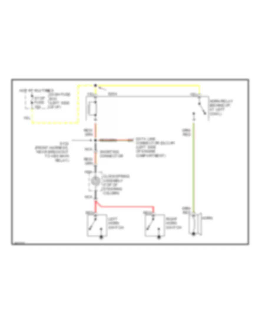
Horn Wiring Diagram for Ford Aspire 1997
List of elements for Horn Wiring Diagram for Ford Aspire 1997:
 English
Horn Wiring Diagram for Ford Aspire 1997
List of elements for Horn Wiring Diagram for Ford Aspire 1997: