HORN
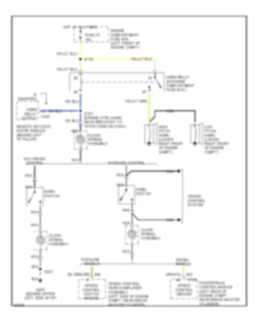
Horn Wiring Diagram for Ford Econoline E250 1997
List of elements for Horn Wiring Diagram for Ford Econoline E250 1997:
- 15a
- C154
- C335
- Clock- spring assembly
- Cruise control system
- Diesel models
- Engine compartment fuse box (left front of engine compt)
- Fuse 27
- G202 (behind upper left side of i/p)
- Gasoline models
- High pitch horn (lower right front of engine compt)
- Horn
- Horn relay (in engine compartment fuse box)
- Horn switch
- Hot at all times
- If equipped
- Low pitch horn (lower right front of engine compt)
- Nca
- Powertrain control module (left rear of engine compt, near brake master cylinder)
- Relay output
- Remote keyless entry module (behind left "b" pillar)
- S116
- S121 (engine ctrl harn, near breakout to 76 pin conn on cowl)
- S207
- Speed control ground
- Speed control servo/amplifier assembly (left side of engine compt, near brake master cylinder)
- Speed control switch ground
- W/cruise control
- W/o cruise control
 English