
HORN
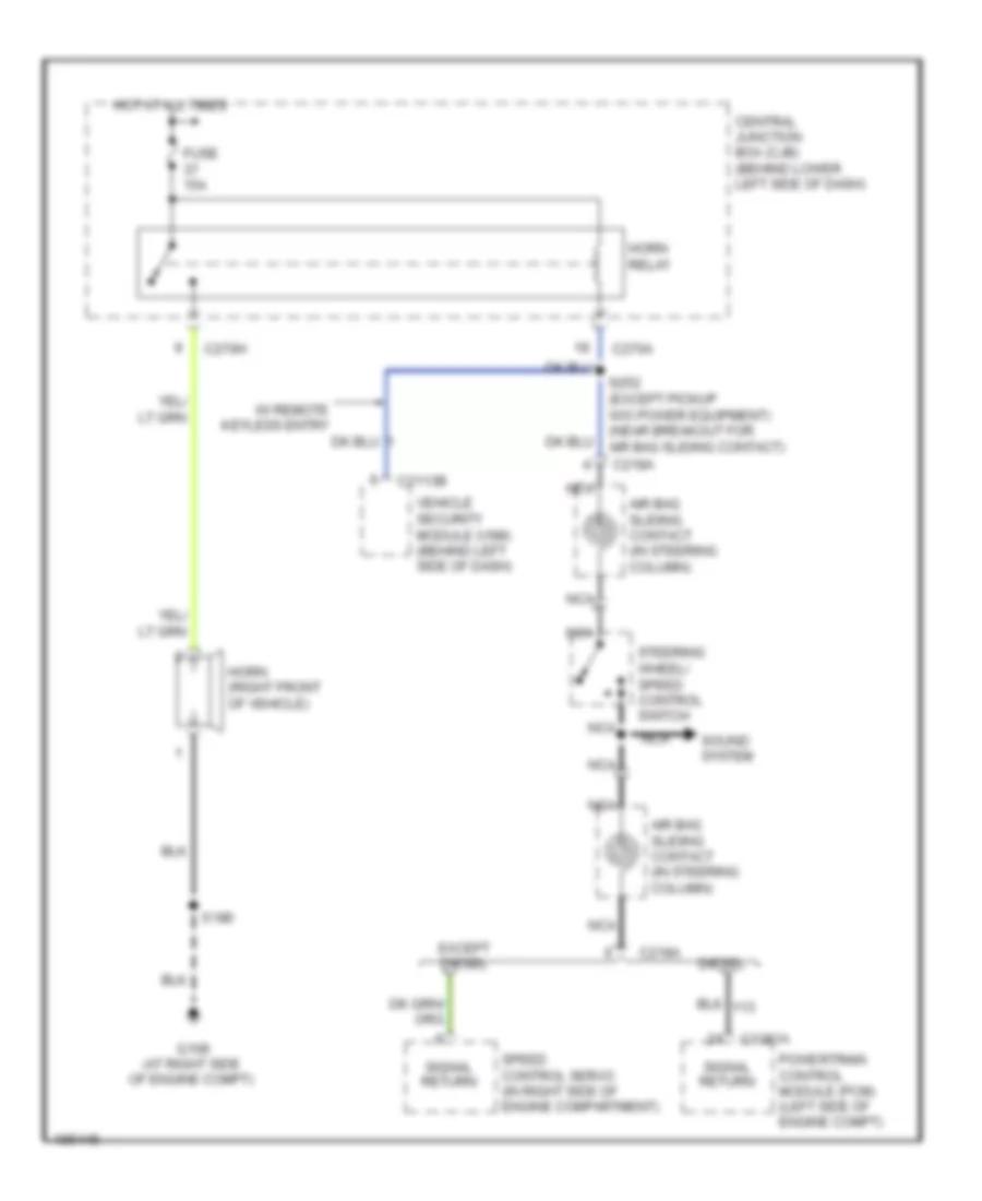
Horn Wiring Diagram for Ford F450 Super Duty 2004
List of elements for Horn Wiring Diagram for Ford F450 Super Duty 2004:
AIR CONDITIONINGANTI-THEFTCOOLING FANANTI-LOCK BRAKESCRUISE CONTROLEXTERIOR LIGHTSENGINE PERFORMANCEHORNINSTRUMENT CLUSTERCOMPUTER DATA LINESHEADLIGHTSGROUND DISTRIBUTIONINTERIOR LIGHTSPOWER DOOR LOCKSPOWER DISTRIBUTIONPOWER MIRRORSPOWER SEATSPOWER WINDOWSWARNING SYSTEMSSHIFT INTERLOCKRADIOSTARTING/CHARGINGSUPPLEMENTAL RESTRAINTSTRANSMISSIONWIPER/WASHER