COMPUTER DATA LINES
Computer Data Lines Wiring Diagram for Nissan Armada SE 2005
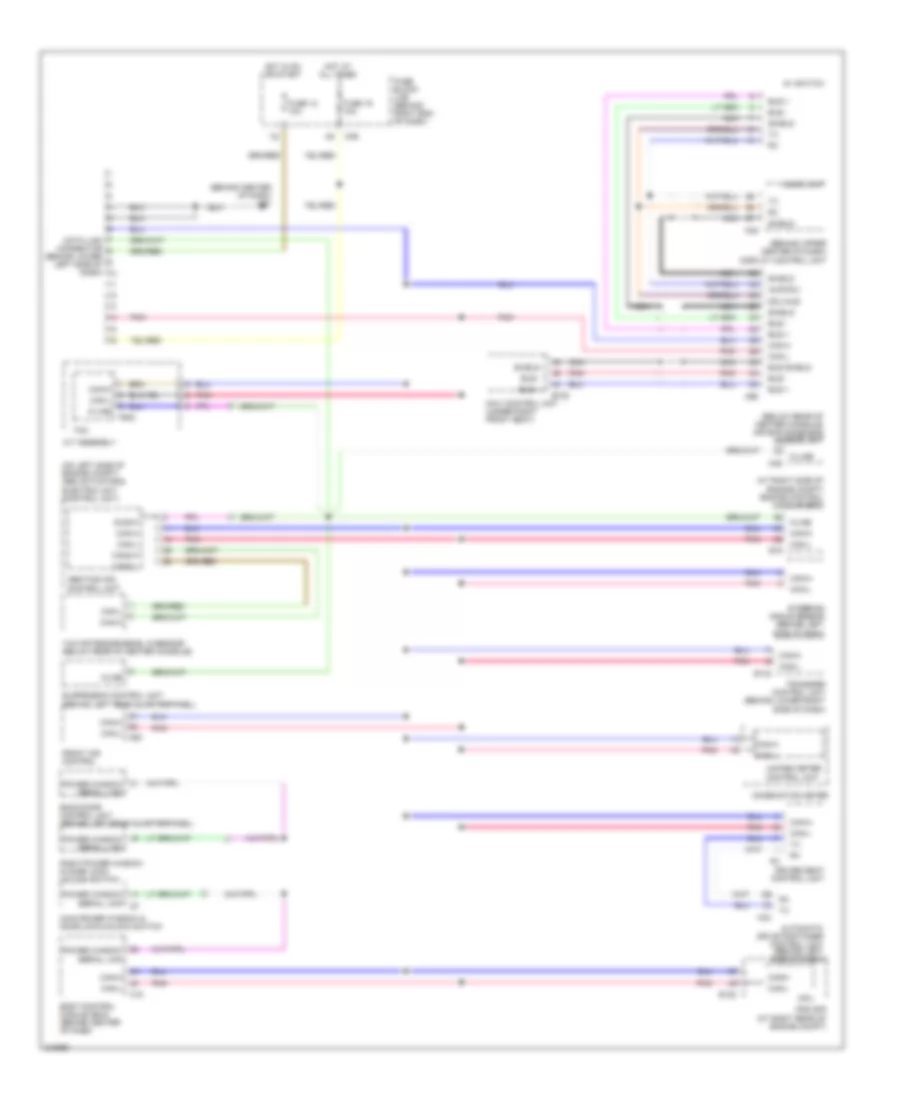
List of elements for Computer Data Lines Wiring Diagram for Nissan Armada SE 2005:
- (at right side of engine compt) engine control module (ecm)
- (behind center of dash) m61
- (behind upper center of dash)
- (below rear of center console) air bag diagnosis sensor unit
- (on left side of engine compt) abs actuator & electric unit (control unit)
- A/t assembly
- Abs/tcs/vdc control unit
- Aud-dcu
- Audio unit
- Automatic drive postioner control unit (behind left side of dash)
- Av switch
- B152
- Back door control unit (behind left rear quarterpanel)
- Body control module (bcm) (behind center of dash)
- Bus +
- Bus -
- Bus shield
- Can-h
- Can-l
- Can-l m50
- Can2-h
- Can2-l
- Combination meter
- Cpu
- Data link connector (behind lower left side of dash)
- Dcu-aud
- Diag-k
- Display control unit
- Driver seat control unit
- E122
- E142
- E16
- F502
- Front air control
- Fuse 12 10a
- Fuse 19 10a
- Fuse block (j/b) (behind right end of dash)
- Hot at all times
- Hot in on or start
- Ipdm e/r (at right rear of engine compt)
- K-line
- Kline
- M18
- M33
- M35
- M39
- M45
- M95
- Main power window & door lock/unlock switch
- Navi control unit (under right front seat)
- Nca
- Pnk
- Power window serial link
- Right power window & door lock/ unlock switch
- Shield
- Steering angle sensor (behind left side of dash)
- Suspension control unit (behind left rear quarterpanel)
- Tcm
- Transfer control unit (behind lower right side of dash)
- Unified meter control unit
- Yaw rate/side/decel g sensor (below rear of center console)
 Čeština
 Dansk
Dansk Deutsch
 Ελληνικά
 English
 English
 Español
 Suomi
Suomi Français
 Français
 עברית
עברית Magyar
 Italiano
 日本語
日本語 한국어
한국어 Nederlands
 Polski
 Português
 Português
 Română
 Русский
 Slovenčina
 Slovenščina
 Svenska
 Türkçe
 中文 (中国)
 Hrvatski