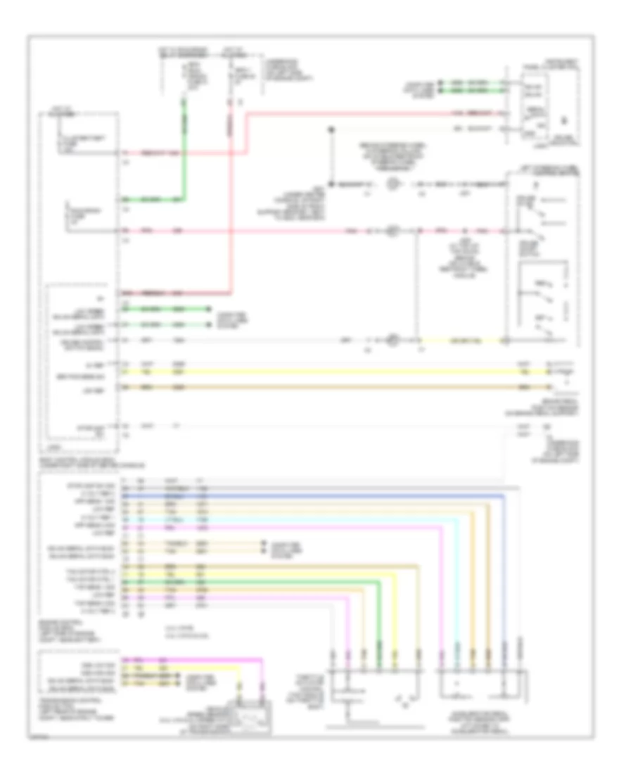
CRUISE CONTROL
Cruise Control Wiring Diagram for Chevrolet Malibu LT 2008
List of elements for Cruise Control Wiring Diagram for Chevrolet Malibu LT 2008:
- (behind steering wheel, in steering column) inflatable restraint steering wheel module coil
- 2.4l (vin 5) & 3.6l
- 2.4l (vin b)
- 5 volt ref 1
- 5 volt ref 2
- 5v ref
- Accelerator pedal position sensor (app) (attached to accelerator pedal)
- App sens 1 sig
- App sens 2 sig
- Body control module (bcm) (under right side of center console)
- Brake pedal position sensor (on brake pedal support)
- Brk pos sens sig
- Cluster/theft fuse 10a
- Computer data lines system
- Cruise control switch signal
- Cruise indicator
- Cruise on ind
- Cruise on/off switch
- D12
- Engine control module (ecm) (left side of engine compt, near battery)
- G201 (under center console, on right side of front support bracket, next to g203, near bcm)
- Gmlan
- Gmlan serial data bus+
- Gmlan serial data bus-
- Gnd
- Hot at all times
- Hot w/ run/crank relay energized
- Ibcm (run/ crank) fuse 21 30a
- Ibcm 1 fuse 20
- Ign
- Instrument panel cluster (ipc)
- J201
- J209 (w/ tap up/ tap down) (behind inflatable restraint wheel module)
- Left steering wheel control switch
- Logic
- Low ref
- Low speed gmlan serial data
- Oss high sig
- Oss low sig
- Pnk
- Res +
- Run/crank fuse 2a
- Serial data
- Set -
- Stoplamp sw
- Stoplamp sw sig
- Tac motor ctrl 1
- Tac motor ctrl 2
- Tan
- Tap sens 1 sig
- Tap sens 2 sig
- Throttle actuator control (tac) module (on throttle body)
- Transmission control module (tcm) (left rear of engine compt, near strut tower)
- Underhood fuse block (on left side of engine compt)
- Vehicle speed sensor (2.4l (vin 5) & 4 speed a/t) (on right side of transmission)
 Čeština
 Dansk
Dansk Deutsch
 Ελληνικά
 English
 English
 Español
 Suomi
Suomi Français
 Français
 עברית
עברית Magyar
 Italiano
 日本語
日本語 한국어
한국어 Nederlands
 Polski
 Português
 Português
 Română
 Русский
 Slovenčina
 Slovenščina
 Svenska
 Türkçe
 中文 (中国)
 Hrvatski