SUPPLEMENTAL RESTRAINTS
Supplemental Restraints Wiring Diagram (1 of 3) for Chevrolet Malibu LT 2008
 https://portal-diagnostov.com/license.html
Automotive Electricians Portal FZCO
Automotive Electricians Portal FZCO
https://portal-diagnostov.com/license.html
https://portal-diagnostov.com/license.html
Automotive Electricians Portal FZCO
Automotive Electricians Portal FZCO
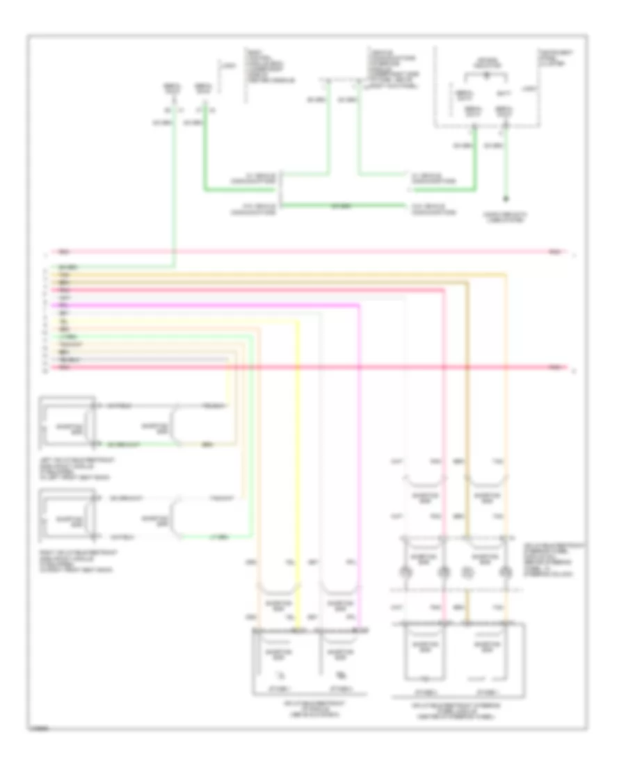
List of elements for Supplemental Restraints Wiring Diagram (1 of 3) for Chevrolet Malibu LT 2008:
- (in right kick panel, forward of g305) g304 computer data lines system
- Air bag (batt) fuse 10a
- Air bag (ign) fuse 10a
- Body control module (bcm) (under right side of center console)
- Case ground
- D11
- Driver inflatable restraint seat belt pretensioner (bottom of left "b" pillar)
- Driver seat belt switch
- Ground
- High control
- Hot at all times
- Hot in run or start
- Ignition 1
- Inflatable restraint sensing & diagnostic module (sdm) (under center console)
- Left front inflatable restraint roof rail module (if equipped) (under headliner, along roof, above both left doors)
- Left inflatable restraint front end sensor (on left side of upper core support)
- Left inflatable restraint side impact sensor (sis) (if equipped) (behind door panel)
- Low control
- Low ref
- Nca
- Occupant sens
- Passenger inflatable restraint seat belt pretensioner (bottom of right "b" pillar)
- Passenger seat belt switch
- Pnk
- Right front inflatable restraint roof rail module (if equipped) (under headliner, along roof, above both right doors)
- Right inflatable restraint front end sensor (on right side of upper core support)
- Right inflatable restraint side impact sensor (sis) (if equipped) (in passenger door)
- Serial data
- Shorting bar
- Signal
- Tan
- Voltage
Supplemental Restraints Wiring Diagram (2 of 3) for Chevrolet Malibu LT 2008
List of elements for Supplemental Restraints Wiring Diagram (2 of 3) for Chevrolet Malibu LT 2008:
- A x1
- Air bag indicator
- B x2
- Batt
- Body control module (bcm) (under right side of center console)
- Computer data lines system
- Inflatable restraint i/p module (above glove box)
- Inflatable restraint steering wheel module (center of steering wheel)
- Inflatable restraint steering wheel module coil (behind steering wheel, in steering column)
- Instrument panel cluster
- Left inflatable restraint side impact module (if equipped) (in left front seat back)
- Logic
- Pnk
- Right inflatable restraint side impact module (if equipped) (in right front seat back)
- Serial data
- Shorting bar
- Stage 1
- Stage 2
- Tan
- Vehicle communications interface module (under right side of dash, above right kick panel)
- W/ vehicle communications
- W/o vehicle communications
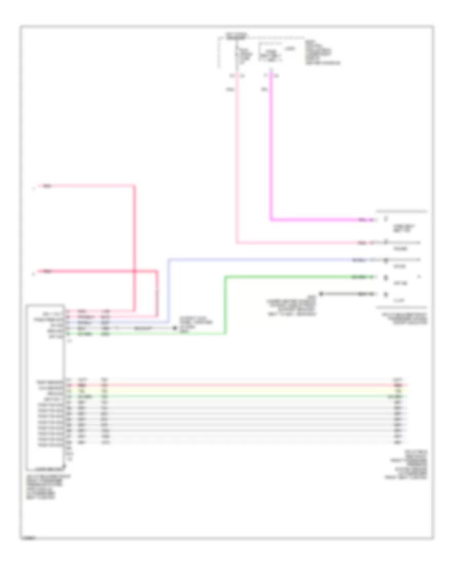
Supplemental Restraints Wiring Diagram (3 of 3) for Chevrolet Malibu LT 2008
List of elements for Supplemental Restraints Wiring Diagram (3 of 3) for Chevrolet Malibu LT 2008:
- (in right kick panel, forward of g305) g304
- B10
- Body control module (bcm) (under right side of center console)
- Case ground
- G203 (under center console, on right side of front support bracket, next to g201, near bcm)
- Ground
- Hot in run or start
- Hum sensor
- Ign 1 volt
- Ignition 1
- Illum
- Inflatable restraint front passenger presence system (pps) module (in passenger seat cushion)
- Inflatable restraint front passenger presence system sensor (in passenger front seat cushion)
- Inflatable restraint passenger air bag on/off indicator
- Logic
- Off ind
- On ind
- Pass pres sig
- Pass seat belt ind
- Pnk
- Position sig
- Power
- Red
- Run/ crank fuse 2a
- Temp sensor

 Čeština
 Dansk
Dansk Deutsch
 Ελληνικά
 English
 English
 Español
 Suomi
Suomi Français
 Français
 עברית
עברית Magyar
 Italiano
 日本語
日本語 한국어
한국어 Nederlands
 Polski
 Português
 Português
 Română
 Русский
 Slovenčina
 Slovenščina
 Svenska
 Türkçe
 中文 (中国)