AIR CONDITIONING
Heater Wiring Diagram, Double Cab for Toyota Tundra Limited 2004
 https://portal-diagnostov.com/license.html
Automotive Electricians Portal FZCO
Automotive Electricians Portal FZCO
https://portal-diagnostov.com/license.html
https://portal-diagnostov.com/license.html
Automotive Electricians Portal FZCO
Automotive Electricians Portal FZCO
List of elements for Heater Wiring Diagram, Double Cab for Toyota Tundra Limited 2004:
- (on left side of engine compt) engine room r/b 2
- (under right side of dash, on hvac housing) blower motor
- Behind upper right end of dash) i2
- Blower resistor (behind right side of dash)
- Blower switch
- Driver side j/b (under left end of dash)
- Engine room j/b (on left side of engine compt)
- Fusible link block (on left side of engine compt)
- Heater fuse 10a
- Heater fuse 50a
- Hot at all times
- Hot in on or start
- Htr relay
- J/c 35 (on left side of engine compt)
- J/c 58 (behind right side of dash)
- Off
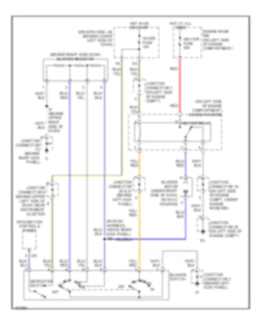
Heater Wiring Diagram, Standard Cab for Toyota Tundra Limited 2004
List of elements for Heater Wiring Diagram, Standard Cab for Toyota Tundra Limited 2004:
- (behind right side dash) blower resistor
- (in dash harness, above right kick panel) i16
- (on left side of engine compartment) engine room r/b
- Blower motor (under right side of dash, on hvac housing)
- Blower switch
- Defroster switch
- Driver's side j/b (behind lower left side of dash)
- Engine room r/b (on left side of engine compartment)
- Gauge fuse 10a
- Heater fuse 50a
- Heater relay
- Hot at all times
- Hot in on or start
- I25
- Integration control & panel
- Junction connector (behind right kick panel)
- Junction connector 1 (on left side of engine compt)
- Junction connector 18 (on left side of engine compt, under engine room r/b)
- Junction connector 25 (on left side of engine compt)
- Junction connector 26 & 27 (behind left kick panel)
- Junction connector 3 (behind left kick panel)
- Junction connector 8 (behind upper left side of dash, near instrument cluster)
- Off
- Red
- Side of dash)
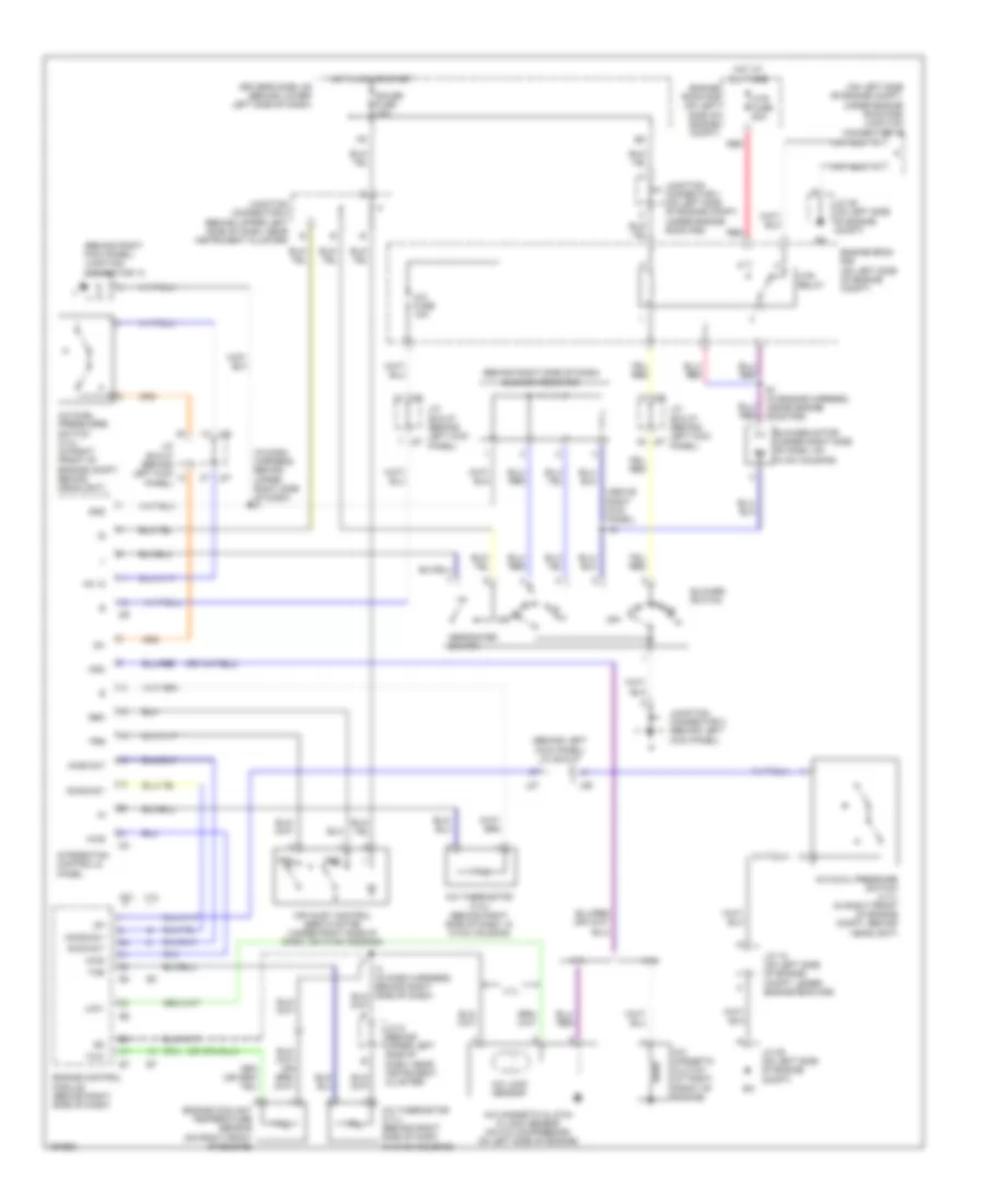
Manual A/C Wiring Diagram, Access/Standard Cab for Toyota Tundra Limited 2004
List of elements for Manual A/C Wiring Diagram, Access/Standard Cab for Toyota Tundra Limited 2004:
- (above right kick panel) i16
- (behind left kick panel) j/c 26 & 27
- (behind right kick panel) junction connector 13
- (behind right side of dash) blower resistor
- (in dash harness, behind upper right side of dash) i4
- (on left side of engine compt, under engine room r/b) junction connector 18
- 3.4l
- 4.7l
- A/c dual pressure switch (4.7l) (in right front of engine compt, behind headlight)
- A/c duel pressusre switch (3.4l) (in right front of engine compt, behind headlight)
- A/c fuse 10a
- A/c lock sensor
- A/c magnetic clutch & lock sensor (on a/c compressor, on left side of engine)
- A/c magnetic clutch (at right front of engine)
- A/c thermistor (3.4l) (behind right side of dash, in hvac housing)
- A/c thermistor (4.7l) (behind right side of dash, in hvac housing)
- A/cs
- Ac +2
- Acid/act
- Acmg/ac1
- Aind/act
- Air inlet control servo motor (under right side of dash, on hvac housing)
- Blower motor (under right side of dash, on hvac housing)
- Blower switch
- Defroster switch
- Driver's side j/b (behind lower left side of dash)
- E1 (in engine harness, inside engine room r/b)
- Engine control module (behind right side of dash)
- Engine coolant temperature sensor (on right front of engine)
- Engine room r/b (on left side of engine compt)
- Frs
- Gauge fuse 10a
- Gnd
- Hot at all times
- Hot in on or start
- Htr fuse 50a
- Htr relay
- I24
- I25
- Ig+
- Integraton control & panel
- J/c 18 (on left side of engine compt, under engine room r/b)
- J/c 25 (on left side of engine compt)
- J/c 26 & 27 (behind left kick panel)
- J/c 9 (behind upper left side of dash, near instrument cluster)
- J26
- J27
- Junction connector 1 (on left side of engine compt, under engine room r/b)
- Junction connector 3 (behind left kick panel)
- Junction connector 8 (behind upper left side of dash, near instrument cluster)
- Lck1
- Mgc
- Off
- Rec
- Red
- The
- Thw
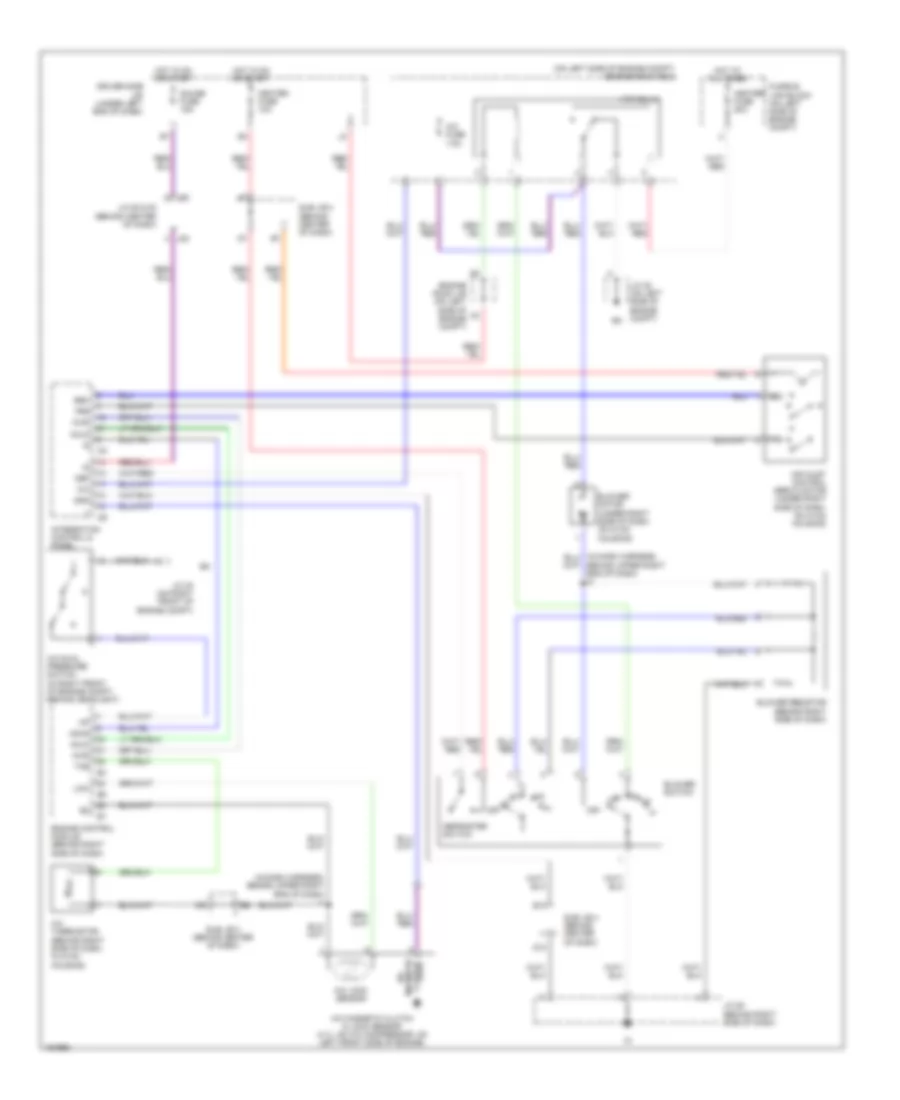
Manual A/C Wiring Diagram, Double Cab for Toyota Tundra Limited 2004
List of elements for Manual A/C Wiring Diagram, Double Cab for Toyota Tundra Limited 2004:
- (in dash harness, behind upper right end of dash) i1
- (on left side of engine compt) engine room r/b 2
- A/c
- A/c dual pressure switch (in right front of engine compt, behind headlight)
- A/c fuse 7.5a
- A/c lock sensor
- A/c magnetic clutch & lock sensor (4.7l: on a/c compressor, on left front side of engine)
- A/c thermistor (behind right side of dash, in hvac housing)
- A/cs
- Acld
- Acmg
- Air inlet control servo motor (under right side of dash, on hvac housing)
- B10
- Behind upper right end of dash) i2
- Blower motor (under right side of dash, on hvac housing)
- Blower resistor (behind right side of dash)
- Blower switch
- D10
- Def
- Defroster switch
- Driver side j/b (under left end of dash)
- Engine control module (behind right side of dash)
- Engine room j/b (on left side of engine compt)
- Frs
- Fusible link block (on left side of engine compt)
- Gauge fuse 15a
- Gnd
- Heater fuse 10a
- Heater fuse 50a
- Hot at all times
- Hot in on or start
- Htr relay
- I24
- I25
- Integration control & panel
- J/c 30 (on right front of engine compt)
- J/c 35 (on left side of engine compt)
- J/c 52 & 53 (behind center of dash)
- J/c 58 (behind right side of dash)
- J52
- J53
- Lcki
- Magnetic clutch
- Off
- Rec
- Sub j/b 3 (behind center of dash)
- Sub j/b 4 (behind center of dash)
- The

 Čeština
 Dansk
Dansk Deutsch
 Ελληνικά
 English
 English
 Español
 Suomi
Suomi Français
 Français
 עברית
עברית Magyar
 Italiano
 日本語
日本語 한국어
한국어 Nederlands
 Polski
 Português
 Português
 Română
 Русский
 Slovenčina
 Slovenščina
 Svenska
 Türkçe
 中文 (中国)