AIR CONDITIONING
Compressor Wiring Diagram for Chevrolet HHR SS 2009
 https://portal-diagnostov.com/license.html
Automotive Electricians Portal FZCO
Automotive Electricians Portal FZCO
https://portal-diagnostov.com/license.html
https://portal-diagnostov.com/license.html
Automotive Electricians Portal FZCO
Automotive Electricians Portal FZCO
List of elements for Compressor Wiring Diagram for Chevrolet HHR SS 2009:
- (2.0l: right rear of engine) (2.4l: right side of engine, near rear of exhaust manifold) (2.2l: top right rear of engine) engine coolant temperature (ect) sensor
- (not used)
- (or 2700)
- (or 5514)
- (or tan)
- 2.0l
- 5 volt ref
- A/c clutch relay 15
- A/c compressor clutch (lower left front of engine)
- A/c fuse 22 10a
- A/c refrigerant pressure sensor (on a/c line, near compressor)
- A/c req sig
- A/c request indicator
- A/c request sig
- A/c request switch
- Batt
- Body control module (bcm) (under center dash, below radio, on right side of center console)
- Computer data lines system
- D12 c1
- Diode a/c clutch diode 9
- Ect sig
- Engine control module (ecm) (left side of engine compt, in front of underhood fuse block)
- Except 2.0l
- F10
- F11 x2
- G109 (on left front shock tower)
- G203 (behind left end of dash)
- Gnd
- Hot at all times
- Hot w/ pwr/trn relay 26 energized
- Hot w/ run/crank relay 51 energized
- Hvac control assembly
- Hvac/ i/p ign fuse 16 10a
- Hvac/pk3 fuse 10 10a
- Ign 1 voltage
- J114 (early production)
- J115 (late production) (in engine harness)
- Logic
- Low ref
- Pnk
- Power distribution system
- Press sens sig
- Rly ctrl
- S101
- S200
- Serial data
- Serial data +
- Serial data -
- Tan
- Underhood fuse block (in engine compt, next to left strut tower)
- X1 d3
- X3 c5
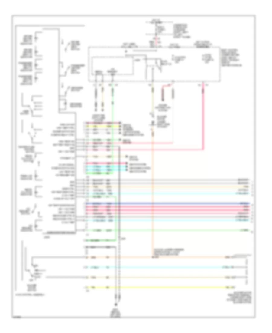
Manual A/C Wiring Diagram (1 of 2) for Chevrolet HHR SS 2009
List of elements for Manual A/C Wiring Diagram (1 of 2) for Chevrolet HHR SS 2009:
- (in hvac jumper harness, approximately 4.9 cm from blower motor) j203
- (not used)
- 5 volt ref
- A/c request indicator
- A/c request sig
- A/c request switch
- Air temp door ctrl
- Air temp door pos sig
- Battery positive
- Bcm 3 fuse 4 30a
- Blower motor (under right side of dash)
- Blower motor resistor assembly (under right side of dash, forward of blower motor)
- Blower motor switch
- Body control module (bcm) (under center dash, below radio, on right side of center console)
- Computer data lines system
- Defogger indicator
- Defogger switch
- Defogger system
- Dimmer switch sig
- Door ctrl
- Driver heated seat hi indicator
- Driver heated seat lo indicator
- Driver heated seat switch
- Fresh air indicator
- G203 (behind left end of dash)
- Gnd
- Hi/low signal
- High
- High temp ctrl
- High temp ind
- High/low sig
- Hot at all times
- Hot w/ run/ crank relay 51 energized
- Htd seat lo
- Hvac control assembly
- Hvac relay 30
- Hvac/ i/p ign fuse 16 10a
- Hvac/pk3 fuse 10 10a
- Ign 1 voltage
- J200
- Logic
- Low
- Low temp ind
- Mode door position sig
- Mode switch
- Off
- Passenger heated seat hi indicator
- Passenger heated seat lo indicator
- Passenger heated seat switch
- Pnk
- Power distribution system
- R defog relay ctrl
- R defog switch sig
- Recir door ctrl a
- Recir door ctrl b
- Recir- culation indicator
- Recir- culation switch
- Seats system
- Seats system interior lights system
- Serial data
- Tan
- Temperature control switch
- Underhood fuse block (in engine compt, next to left strut tower)
- Wake up volt off
- X2 f6
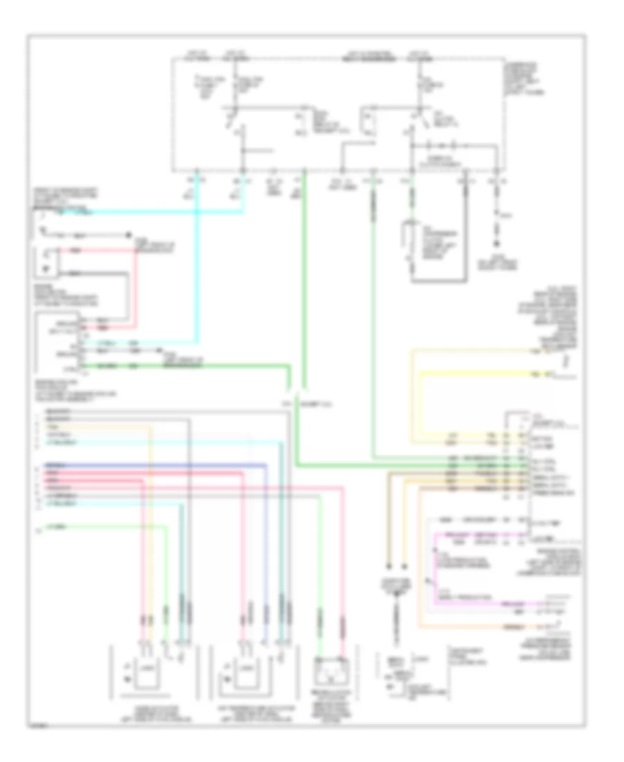
Manual A/C Wiring Diagram (2 of 2) for Chevrolet HHR SS 2009
List of elements for Manual A/C Wiring Diagram (2 of 2) for Chevrolet HHR SS 2009:
- (2.0l: right rear of engine) (2.4l: right side of engine, near rear of exhaust manifold) (2.2l: top right rear of engine) engine coolant temperature (ect) sensor
- (front of engine compt, attached to radiator) (except 2.0l) engine cooling fan
- (not used)
- (or 2700)
- (or 5514)
- (or tan)
- 2.0l
- 5 volt ref
- A/c clutch relay 15
- A/c compressor clutch (lower left front of engine)
- A/c fuse 22 10a
- A/c refrigerant pressure sensor (on a/c line, near compressor)
- Air temperature actuator (center of dash, left side of hvac module)
- Computer data lines system
- Cool fan fuse 40 30a
- Cool fan fuse 7 (2.0l) 40a
- Cool fan relay 50 (except 2.0l)
- Coolant temperature ind
- Ctrl
- D12 x1
- D3 x1
- Diode a/c clutch diode 9
- Ect sig
- Engine control module (ecm) (left side of engine compt, in front of underhood fuse block)
- Engine cooling fan (front of engine compt, attached to radiator)
- Engine cooling fan module (attached to engine cooling fan motor assembly)
- Except 2.0l
- F10
- F11 x2
- G105 (left front of engine block)
- G109 (on left front shock tower)
- Ground
- Hot at all times
- Hot w/ pwr/trn relay 26 energized
- Ign
- Instrument panel cluster (ipc)
- J114 (early production)
- J115 (late production) (in engine harness)
- Logic
- Low ref
- Mode actuator (center of dash, left side of hvac module)
- Pnk
- Press sens sig
- Recirculation actuator (behind right side of dash, above blower motor)
- Red
- Rly ctrl
- S101
- Serial data
- Serial data +
- Serial data -
- Splt volt
- Tan
- Underhood fuse block (in engine compt, next to left strut tower)
- X1 b2
- X2 a5
- X3 c5

 Čeština
 Dansk
Dansk Deutsch
 Ελληνικά
 English
 English
 Español
 Suomi
Suomi Français
 Français
 עברית
עברית Hrvatski
 Italiano
 日本語
日本語 한국어
한국어 Nederlands
 Polski
 Português
 Português
 Română
 Русский
 Slovenčina
 Slovenščina
 Svenska
 Türkçe
 中文 (中国)