CRUISE CONTROL
Cruise Control Wiring Diagram for Mercedes-Benz E320 2008
 https://portal-diagnostov.com/license.html
Automotive Electricians Portal FZCO
Automotive Electricians Portal FZCO
https://portal-diagnostov.com/license.html
https://portal-diagnostov.com/license.html
Automotive Electricians Portal FZCO
Automotive Electricians Portal FZCO
List of elements for Cruise Control Wiring Diagram for Mercedes-Benz E320 2008:
- Accelerate and set
- Accelerator pedal sensor (top of accelerator pedal assembly)
- C29
- Can-bh
- Can-bl
- Can-ch
- Can-cl
- Cdi control
- Computer data lines system
- Cruise control switch
- Decelerate and set
- E pwg1
- Electronic control unit
- Engine controls system
- Fuse 15a
- Hot at all times
- Interior fuse box (left end of dash)
- M pwg1
- M pwg2
- Module (left rear of engine compt)
- Off
- Output speed sensor
- Poti -
- Poti sig
- Red
- Resume from memory
- Steering column module (top of steering column)
- Throttle valve actuator (right front of engine)
- U pwg1
- Vcs (sbs) switch
- W15/1 (near right kick panel)
Electronic Accelerator/Cruise/Idle Speed Control Wiring Diagram for Mercedes-Benz E320 2008
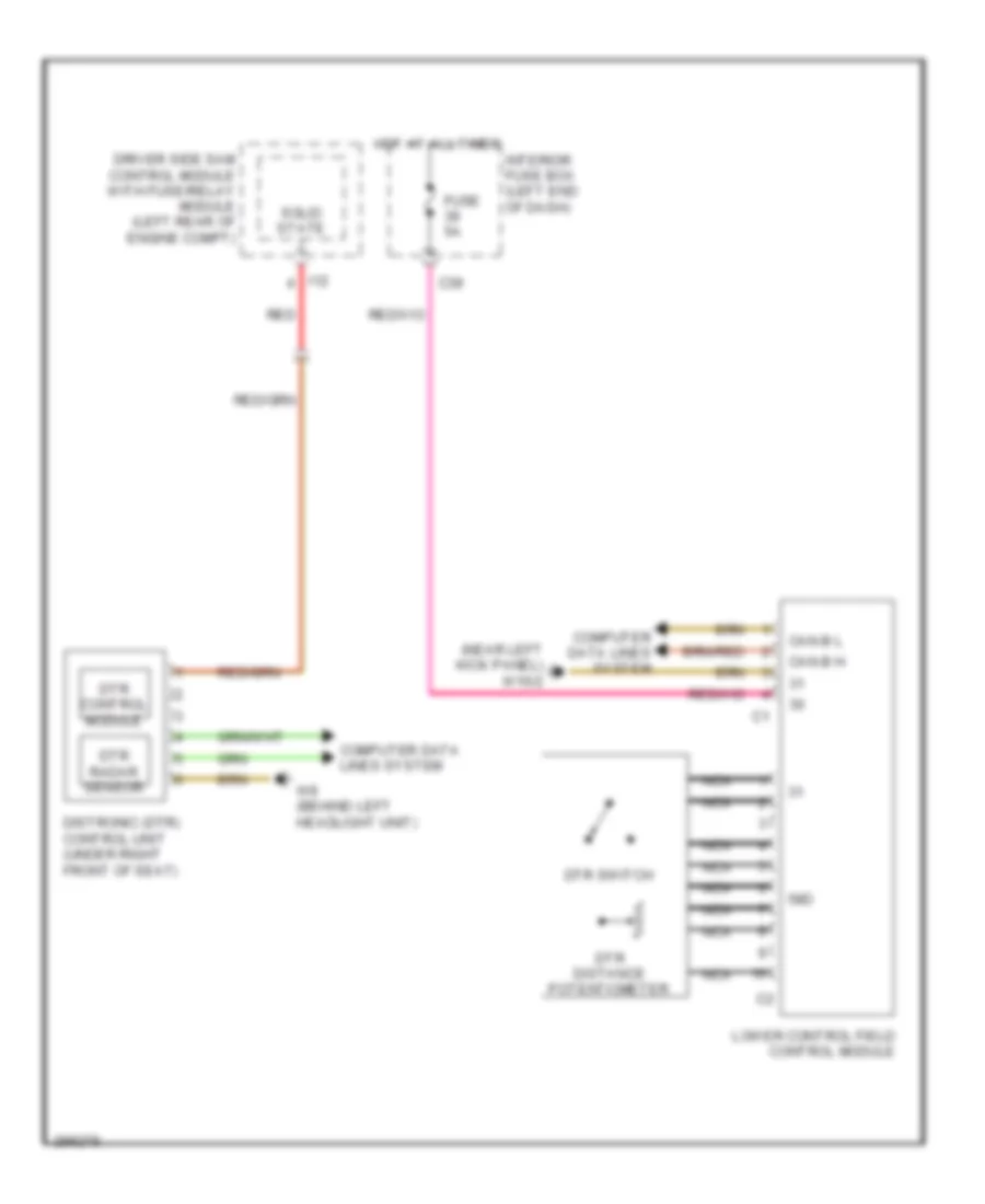
List of elements for Electronic Accelerator/Cruise/Idle Speed Control Wiring Diagram for Mercedes-Benz E320 2008:
- (near left kick panel) w15/2
- 58d
- C39
- Can-b h
- Can-b l
- Computer data lines system
- Distronic (dtr) control unit (under right front of seat)
- Driver side sam control module with fuse/relay module (left rear of engine compt)
- Dtr control module
- Dtr distance potentiometer
- Dtr radar sensor
- Dtr switch
- Fuse 5a
- Hot at all times
- I12
- Interior fuse box (left end of dash)
- Lower control field control module
- Nca
- Red
- Solid state
- W9 (behind left headlight unit)

 Čeština
 Dansk
Dansk Deutsch
 Ελληνικά
 English
 English
 Español
 Suomi
Suomi Français
 Français
 עברית
עברית Hrvatski
 Italiano
 日本語
日本語 한국어
한국어 Nederlands
 Polski
 Português
 Português
 Română
 Русский
 Slovenčina
 Slovenščina
 Svenska
 Türkçe
 中文 (中国)