HEADLIGHTS
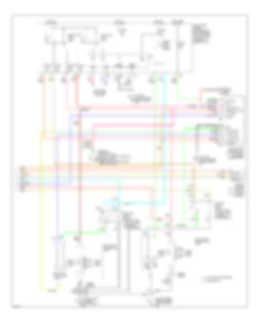
Headlights Wiring Diagram, with DRL (1 of 2) for Infiniti G35 2004
 https://portal-diagnostov.com/license.html
Automotive Electricians Portal FZCO
Automotive Electricians Portal FZCO
https://portal-diagnostov.com/license.html
https://portal-diagnostov.com/license.html
Automotive Electricians Portal FZCO
Automotive Electricians Portal FZCO
List of elements for Headlights Wiring Diagram, with DRL (1 of 2) for Infiniti G35 2004:
- 12a
- 15a
- 2b m5
- 8a m4
- Acc
- Autolight sens
- Bat
- Body control module (bcm) (behind left kick panel)
- Can-h
- Can-l
- Charge ind
- Comb sw in 1
- Comb sw in 2
- Comb sw in 3
- Comb sw in 4
- Comb sw in 5
- Comb sw out 1
- Comb sw out 2
- Comb sw out 3
- Comb sw out 4
- Comb sw out 5
- Combination meter
- Combination switch
- Computer data lines system
- Coupe
- Diode
- E102
- Fuse & fusible link block (at right rear of engine compt)
- Fuse 10a
- Fuse block (j/b) (behind left kick panel)
- Fusible link f 50a
- Gnd
- High beam ind
- Hot at all times
- Hot in acc or on
- Hot in on or start
- Hot in start
- Ign
- Input 1
- Input 2
- Input 3
- Input 4
- Input 5
- M30 (behind instrument cluster)
- M66 (behind right side of dash)
- Output 1
- Output 2
- Output 3
- Output 4
- Output 5
- Pnk
- Red
- Sedan
- Sensor gnd
- Sensor in
- Starting/ charging system
- Unified meter control unit
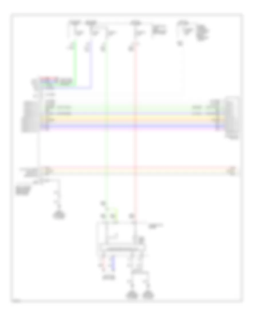
Headlights Wiring Diagram, with DRL (2 of 2) for Infiniti G35 2004
List of elements for Headlights Wiring Diagram, with DRL (2 of 2) for Infiniti G35 2004:
- (on left front side of engine compartment) e43
- (on right side of engine compartment) e17
- Alt-l
- Can-h
- Can-l
- Computer data lines system
- Cpu
- Daytime light control unit (at right front corner of engine compt)
- Daytime light relay 1 (in relay box, at right rear of engine compartment)
- Daytime light relay 2 (in relay box, at right rear of engine compartment)
- Dimmer switch
- E25
- E26
- Fog head- lamp high
- Fr fog
- Front fog lamp relay
- Fuse 10a
- Fuse 15a
- Gnd
- Gnd (power)
- Gnd (signal)
- Ground
- H/lp hi
- H/lp lo
- Head- fog lamp
- Head- lamp low
- Headlamp high relay
- Headlamp low relay
- Hid cont
- Hot at all times
- Hot in on or start
- Ignition
- Intelligent power distribution module engine room (ipdm e/r) (at right rear corner of engine compt)
- Lamp
- Lamp high
- Left front combination lamp
- Lt fuse
- Lt lmp gnd
- Lt main lmp
- Main switch
- Optical sensor (w/ autolight option) (at top right of dash)
- Output
- Parking brake switch (coupe: at base of parking brake lever) (sedan: on parking brake pedal bracket)
- Pkb switch
- Pnk
- Power
- Red
- Right front combination lamp
- Rt fuse
- Rt main lmp
- Sedan coupe
- Start
- Starting/ charging system
- W/ halogen bulb (sedan)
- W/ xenon bulb
Headlights Wiring Diagram, without DRL (1 of 2) for Infiniti G35 2004
List of elements for Headlights Wiring Diagram, without DRL (1 of 2) for Infiniti G35 2004:
- 12a
- 15a
- Acc
- Autolight sens
- Bat
- Body control module (bcm) (behind left kick panel)
- Can-h
- Can-l
- Comb sw in 1
- Comb sw in 2
- Comb sw in 3
- Comb sw in 4
- Comb sw in 5
- Comb sw out 1
- Comb sw out 2
- Comb sw out 3
- Comb sw out 4
- Comb sw out 5
- Combination meter
- Combination switch
- Computer data lines
- Computer data lines system
- Fuse & fusible link block (at right rear of engine compt)
- Fuse 1 10a
- Fuse 14 10a
- Fuse 19 10a
- Fuse 6 10a
- Fuse block (j/b) (behind left kick panel)
- Fusible link f 50a
- Gnd
- High beam ind
- Hot at all times
- Hot in acc or on
- Hot in on or start
- Ign
- Input 1
- Input 2
- Input 3
- Input 4
- Input 5
- M30 (behind instrument cluster)
- M66 (behind right side of dash)
- Output 1
- Output 2
- Output 3
- Output 4
- Output 5
- Pnk
- Red
- Sensor gnd
- Sensor in
- Unified meter control unit
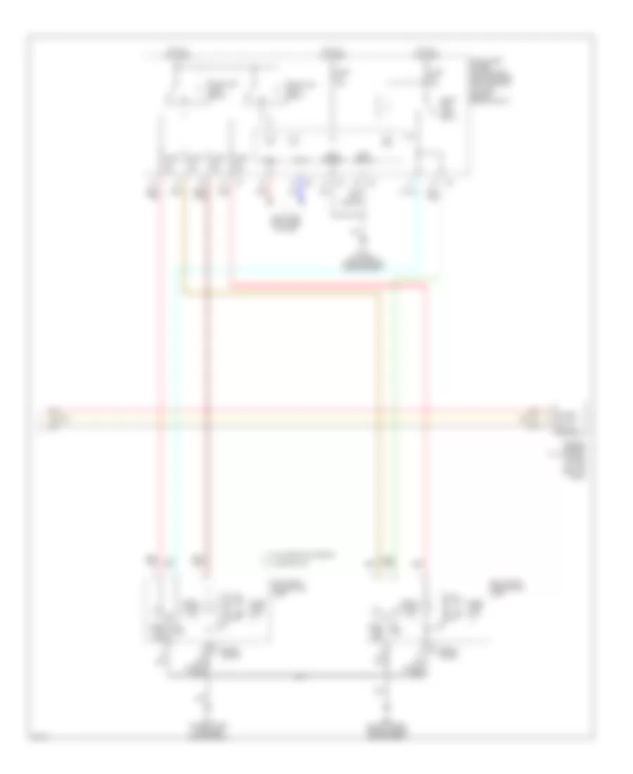
Headlights Wiring Diagram, without DRL (2 of 2) for Infiniti G35 2004
List of elements for Headlights Wiring Diagram, without DRL (2 of 2) for Infiniti G35 2004:
- Can-h
- Can-l
- Computer data lines system
- Cpu
- E17 (on right side of engine compartment)
- E43 (on left front side of engine compartment)
- Fr fog
- Front fog lamp relay
- Fuse 10a
- Fuse 15a
- Gnd (power)
- Gnd (signal)
- Ground
- H/lp hi
- H/lp lo
- Head- fog lamp
- Head- fog lamp lamp high
- Head- lamp low
- Headlamp high relay
- Headlamp low relay
- Hid cont
- Hot at all times
- Intelligent power distribution module engine room (ipdm e/r) (at right rear of engine compt)
- Lamp high
- Left front combination lamp
- Optical sensor (w/ autolight option) (at top right of dash)
- Output
- Pnk
- Power
- Red
- Right front combination lamp
- Sedan coupe
- W/ halogen bulb (sedan)
- W/ xenon bulb

 Čeština
 Dansk
Dansk Deutsch
 Ελληνικά
 English
 English
 Español
 Suomi
Suomi Français
 Français
 עברית
עברית Hrvatski
 Magyar
 日本語
日本語 한국어
한국어 Nederlands
 Polski
 Português
 Português
 Română
 Русский
 Slovenčina
 Slovenščina
 Svenska
 Türkçe
 中文 (中国)