INSTRUMENT CLUSTER
2.6L
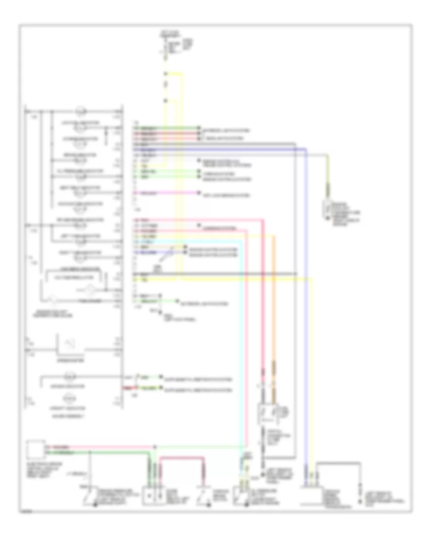
2.6L, Instrument Cluster Wiring Diagram, Early Production for Isuzu Rodeo S 1995
 https://portal-diagnostov.com/license.html
Automotive Electricians Portal FZCO
Automotive Electricians Portal FZCO
https://portal-diagnostov.com/license.html
https://portal-diagnostov.com/license.html
Automotive Electricians Portal FZCO
Automotive Electricians Portal FZCO
List of elements for 2.6L, Instrument Cluster Wiring Diagram, Early Production for Isuzu Rodeo S 1995:
- A10
- A11
- A12
- B10
- B11
- B12
- Brake warning light
- C211
- C274
- C275
- Charge warning light
- Charging system (generator)
- Check engine malfunction indicator lamp
- Combination valve pressure differential switch (in brake fluid valve)
- Dash fuse box
- Diode box d
- Engine control module (ecm) (left kick panel)
- Engine controls system (diode box a)
- Engine controls system (engine control module ecm)
- Engine coolant temperature (ect) gauge sender (right side of engine below intake manifold)
- Engine coolant temperature gauge
- Exterior lights system (combination switch)
- Fuel gauge
- Fuel tank unit (right front of fuel tank)
- Fuse 10a
- G200 (left side kick panel)
- G415 (under body, ahead of rear bumper)
- Headlights system
- Hi beam indicator light
- Hot in on or start
- Illumination (2 bulbs w/ tachometer) (9 bulbs w/o tachometer)
- Indicator cancel switch
- Instrument cluster
- Interior lights system
- Internal voltage regulator
- Left turn indicator light
- Low fuel warning light
- O2 sensor indicator light
- Oil pressure switch (lower front of engine)
- Oil pressure warning light
- Parking brake switch (on parking brake lever)
- Pnk
- Rear wheel anti-lock brake controller (below right front seat)
- Red
- Right turn indicator light
- Rr antilock brake warning light
- Seatbelt warning light
- Vehicle speed sensor
- Warning system (warning buzzer control unit)
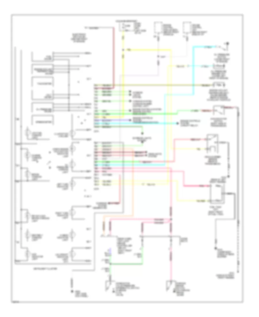
2.6L, Instrument Cluster Wiring Diagram, Late Production for Isuzu Rodeo S 1995
List of elements for 2.6L, Instrument Cluster Wiring Diagram, Late Production for Isuzu Rodeo S 1995:
- (left rear of eng compt, 0n inner fender panel) g104
- (left rear of eng compt, on inner fender panel)
- (not used)
- (pigtail connection in 1995 only)
- 1-15
- Air bag indicator
- Anti-lock brake system
- Brake indicator
- Brake pressure differential switch (left rear of engine compt)
- Charge indicator
- Charging system
- Dash fuse box
- Diode box d (below left side of i/p)
- Electronic brake control module (below right front seat)
- Engine controls & cruise control systems
- Engine controls system
- Engine coolant temperature gauge
- Engine coolant temperature sender (right side of engine)
- Exterior lights system
- Fuel gauge
- Fuel tank unit
- G104
- G200 (left kick panel)
- Gauge assembly
- Headlights system
- High beam indicator
- Hot in on or start
- I-16
- I-28
- Left turn indicator
- Low fuel indicator
- Malfunction indicator
- Meter cb-7 15a
- Oil pressure indicator
- Oil pressure switch (lower right side of engine)
- Only
- Parking brake switch
- Pnk
- Red
- Right turn indicator
- Rr abs brake indicator
- Seat belt indicator
- Speedometer
- Upshift indicator
- Vehicle speed sensor (rear of transmission)
- Voltage regulator
- Warning system
3.2L
3.2L, Instrument Cluster Wiring Diagram, Early Production for Isuzu Rodeo S 1995
List of elements for 3.2L, Instrument Cluster Wiring Diagram, Early Production for Isuzu Rodeo S 1995:
- 4wd indicator light
- 4wd indicator switch (right side of transmission)
- A10
- A11
- A12
- A13
- A14
- B10
- B11
- B12
- B13
- B14
- Brake warning light
- C274
- C275
- Charge warning light
- Charging system (generator)
- Check engine malfunction indicator lamp
- Combination valve pressure differential switch (in brake fluid valve)
- Cruise control unit (behind right side of i/p)
- Dash fuse box (left side of i/p)
- Diode box d
- Electronic ignition (ei) (center front of engine)
- Engine control module (ecm) (behind front console)
- Engine controls system (engine control module ecm)
- Engine controls system (transmission switch)
- Engine controls system (upshift relay)
- Engine coolant temperature gauge
- Engine coolant temperaure (ect) gauge sender (rear of engine in coolant manifold)
- Exterior lights system
- Fuel gauge
- Fuel tank unit (right front of fuel tank)
- Fuse 10a
- G101 (middle of right front fender)
- G104 (rear of left front fender)
- G200 (left side kick panel)
- G415 (under body, ahead of rear bumper)
- Headlights system
- Hi beam indicator light
- Hot in on or start
- Illumination (4 bulbs)
- Instrument cluster
- Interior lights system
- Left turn indicator light
- Low fuel warning light
- Oil pressure gauge
- Oil pressure sender unit (lower left front of engine)
- Oil pressure switch (lower front of engine)
- Oil pressure warning light
- Parking brake switch (on parking brake lever)
- Pnk
- Rear wheel anti-lock brake controller (below right front seat)
- Right turn indicator light
- Rr antilock brake warning light
- Seatbelt warning light
- Speedometer
- Tachometer
- U/s upshift indicator light (m/t)
- Vehicle speed sensor (rear of transmission)
- Volt meter
- Warning system (warning buzzer control unit)
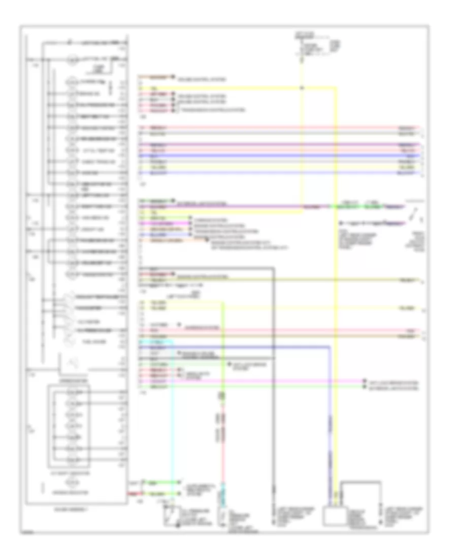
3.2L, Instrument Cluster Wiring Diagram, Late Production (1 of 2) for Isuzu Rodeo S 1995
List of elements for 3.2L, Instrument Cluster Wiring Diagram, Late Production (1 of 2) for Isuzu Rodeo S 1995:
- (1995 a/t)
- (1995)
- (1996)
- (exc 95 a/t)
- (left rear corner of eng compt, on inner fender panel) g104
- 4wd ind
- A/t oil temp ind
- A/t shift indicator
- Abs active ind
- Air bag indicator
- Anti-lock brake system
- Brake ind
- Charge ind
- Charging system
- Check trans ind
- Coolant temp gauge
- Cruise control system
- Cruise main ind
- Cruise set ind
- Dash fuse box
- Engine & cruise control systems
- Engine controls system
- Engine controls system (m/t)
- Exterior lights system
- Front axle switch (on front axle)
- Fuel gauge
- G104 (left rear corner of engine compt, on inner fender panel)
- G200 (left kick panel)
- Gauge assembly
- Headlights system
- High beam ind
- Hot in on or start
- I-15
- I-16
- I-26
- I-27
- I-28
- Left turn ind
- Low fuel ind
- Malfunction ind
- Meter fuse cb-7 15a
- Oil press gauge
- Oil pressure ind
- Oil pressure sending unit (lower left side of engine)
- Oil pressure switch (lower left side of engine)
- Or transmission control system (a/t)
- Pnk
- Power drive ind
- Red
- Right turn ind
- Rr abs brake ind
- Seat belt ind
- Speedometer
- Tachometer
- Timer (1995)
- Transmission controls system
- Upshift ind
- Vehicle speed sensor (rear of transmission)
- Voltmeter
- Warning system
- Winter drive ind
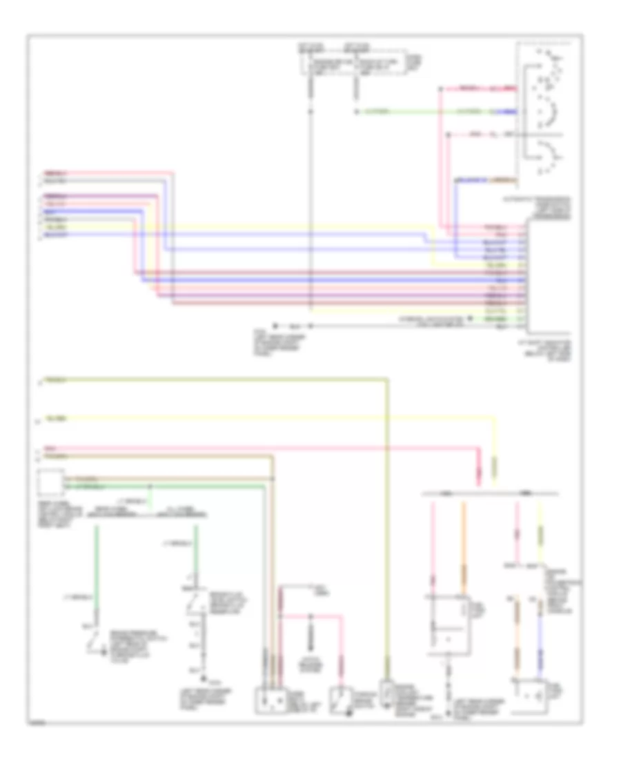
3.2L, Instrument Cluster Wiring Diagram, Late Production (2 of 2) for Isuzu Rodeo S 1995
List of elements for 3.2L, Instrument Cluster Wiring Diagram, Late Production (2 of 2) for Isuzu Rodeo S 1995:
- (left rear corner of engine compt, on inner fender panel)
- (not used)
- A/t shift indicator controller (below left side of dash)
- All wheel anti-lock brakes
- Automatic transmission mode switch (left side of transmission)
- B15
- Back-up turn fuse cb-15 15a
- Brake fluid level switch (brake fluid reservoir)
- Brake pressure differential switch (left rear of engine compt, in brake fluid valve)
- C13
- Dash fuse box
- Diode box d (below left side of i/p)
- Engine coolant temperature sender (right side of engine)
- Engine device fuse cb-3 15a
- Engine or powertrain control module (behind front console)
- Fuel tank unit
- G104
- G104 (left rear corner of engine compt, on inner fender panel)
- Hatch release system
- Hot in on or start
- Interior lights system (taillight relay)
- Parking brake switch
- Pnk
- Rear wheel anti-lock brake control module (below right front seat)
- Rear wheel anti-lock brakes

 Čeština
 Dansk
Dansk Deutsch
 Ελληνικά
 English
 English
 Español
 Suomi
Suomi Français
 Français
 עברית
עברית Hrvatski
 Magyar
 日本語
日本語 한국어
한국어 Nederlands
 Polski
 Português
 Português
 Română
 Русский
 Slovenčina
 Slovenščina
 Svenska
 Türkçe
 中文 (中国)