POWER DISTRIBUTION
3.0L SC
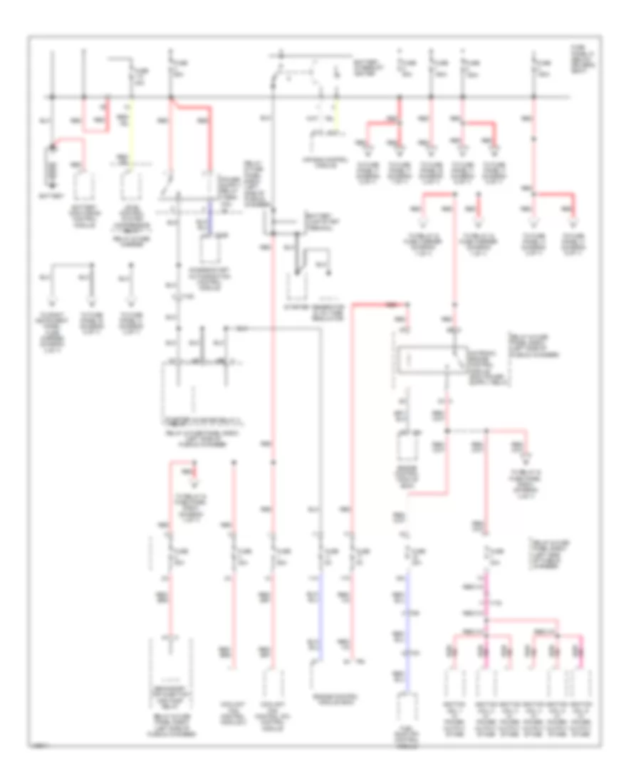
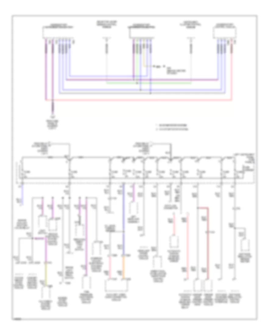
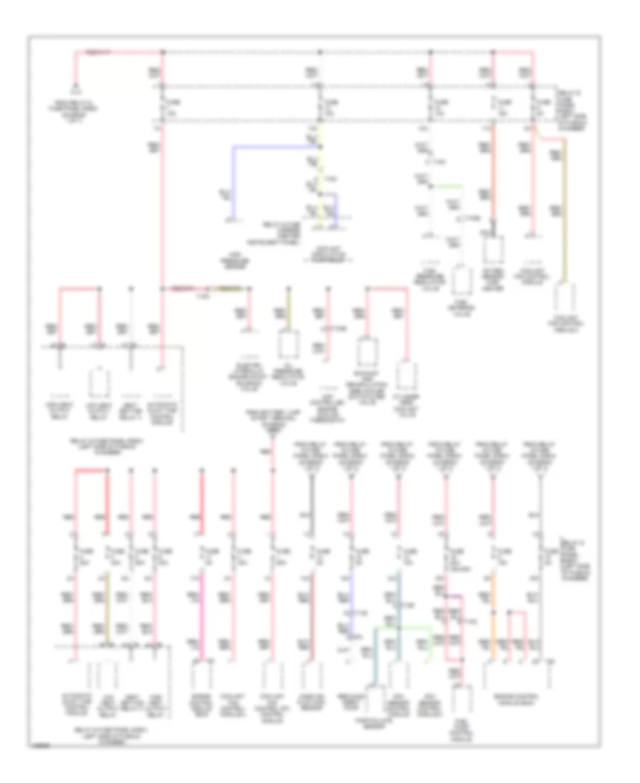
3.0L SC, Power Distribution Wiring Diagram (1 of 7) for Audi Q7 Prestige S 2013
List of elements for 3.0L SC, Power Distribution Wiring Diagram (1 of 7) for Audi Q7 Prestige S 2013:
- 11a
- 15)
- 16a
- 17a
- Access/start authorization control module
- Air bag control module
- Battery
- Battery interrupt igniter
- Battery jump start terminal
- Battery monitoring control module
- Coolant fan control (fc) control module
- Coolant fan control module 2
- Engine control module (ecm)
- Fuel pump (fp) control module
- Fuse 150a
- Fuse 30a
- Fuse 40a
- Fuse 50a
- Fuse 5a
- Fuse 60a
- Fuse panel d (below driver's seat)
- Generator & voltage regulator
- Ignition coil 1 w/ power output stage
- Ignition coil 2 w/ power output stage
- Ignition coil 3 w/ power output stage
- Ignition coil 4 w/ power output stage
- Ignition coil 5 w/ power output stage
- Ignition coil 6 w/ power output stage
- Inal
- Level control system compressor relay
- Red
- Relay & fuse carrier
- Relay & fuse panel e-box (left side of plenum chamber)
- Secondary air injection (air) pump relay
- Starter
- Starter relay
- Starter relay 2
- T10d
- T17d
- T20e
- T2k
- T6k
- T94
- To fuse panel b (diagram 2 of 7)
- To fuse panel b (diagram 5 of 7)
- To fuse panel c (diagram 2 of 7)
- To fuse panel c (diagram 3 of 7)
- To fuse panel c (diagram 6 of 7)
- To fuse panel f (diagram 5 of 7)
- To fuse panel f (diagram 6 of 7)
- To fuse panel f (diagram 7 of 7)
- To relay & fuse carrier (diagram 7 of 7)
- To relay & fuse panel e-box (diagram 4 of 7)
- To right instrument panel fuse carrier (diagram 3 of 7)
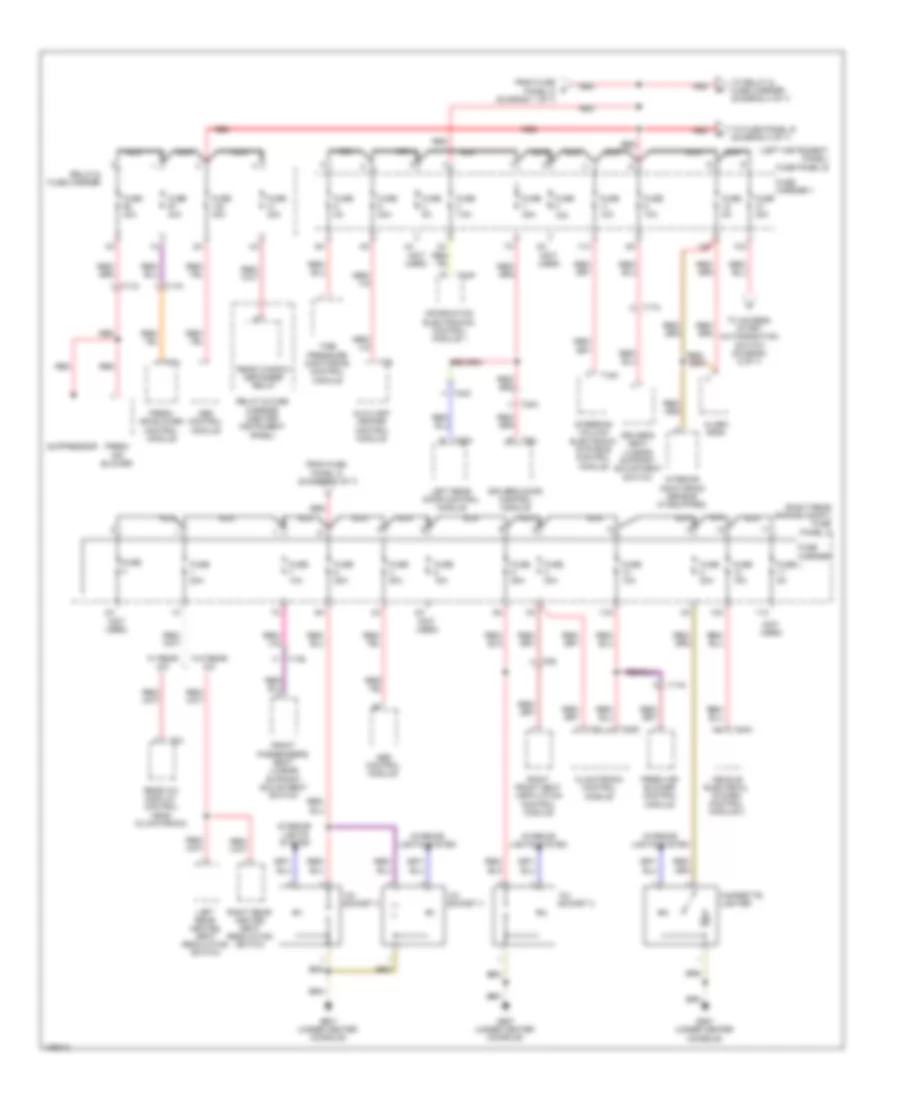
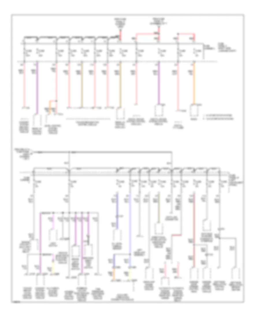
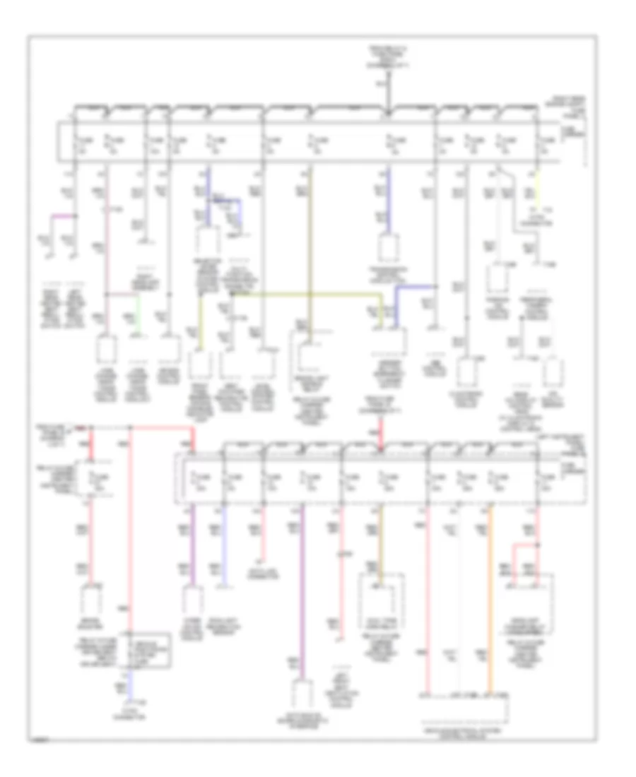
3.0L SC, Power Distribution Wiring Diagram (2 of 7) for Audi Q7 Prestige S 2013
List of elements for 3.0L SC, Power Distribution Wiring Diagram (2 of 7) for Audi Q7 Prestige S 2013:
- (left instrument panel) fuse panel b
- (not used)
- (right rear engine compt) fuse panel c
- 10a
- 11a
- 12a
- 12v socket 2
- 12v socket 3
- 12v socket 4
- Abs control module
- Alarm horn
- Auxiliary heater control module
- Cigarette lighter
- Climatronic control module
- Driver's door control module
- Driver's seat lumbar support adjustment switch
- Fresh air blower
- Fresh air blower control module
- From fuse panel d (diagram 1 of 7)
- Front passenger's seat lumbar support adjustment switch
- Fuse
- Fuse 10a
- Fuse 15a
- Fuse 20a
- Fuse 25a
- Fuse 30a
- Fuse 35a
- Fuse 40a
- Fuse 5a
- Fuse 7.5a
- Fuse carrier
- Fuse carrier 1
- G687 (under center console)
- Information electronics control module 1
- Interior lights system
- Interior monitoring sensor (if equipped)
- Left rear door control module
- Left rear heated seat regulating switch
- Nca
- Rear a/c display control head (climatronic)
- Rear window defogger relay
- Red
- Relay & fuse carrier
- Relay & fuse carrier (center instrument panel)
- Right front seat ventilation control module
- Right rear heated seat regulating switch
- Steering column electronic systems control module
- Suppressor
- T16a
- T16d
- T17a
- T17b
- T17h
- T17k
- T20a
- T20c
- T20l
- T20n
- T2b
- T3c
- T3h
- T40a
- T6ai
- T6g
- T8af
- Tire pressure monitoring control module
- To access/ start authorization switch (diagram 6 of 7)
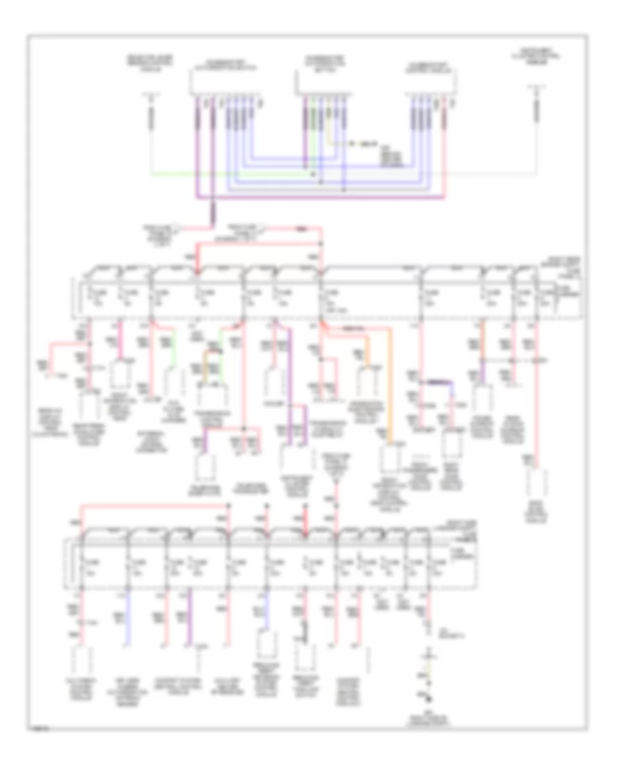
- To fuse panel b (diagram 3 of 7)
- To relay & fuse carrier (diagram 3 of 7)
- Vehicle electrical system control module 2
- W/ rear a/c
- W/o rear a/c
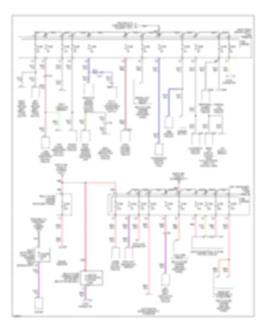
3.0L SC, Power Distribution Wiring Diagram (3 of 7) for Audi Q7 Prestige S 2013
List of elements for 3.0L SC, Power Distribution Wiring Diagram (3 of 7) for Audi Q7 Prestige S 2013:
- (left instrument panel) fuse panel b
- (right rear engine compt) fuse panel c
- 10a
- 11a
- 12 pin connector
- 12a
- 18 pin connector
- Abs control module
- Air bag control module
- Air quality sensor
- Asr/esp button
- Brake booster
- Brake light disable relay
- Climatronic control module
- Cooler
- Cooler fuse 5a
- Data bus on board diagnostic interface
- Data link connector
- Dual horn relay
- From fuse panel b (diagram 2 of 7)
- From relay & fuse panel e-box (diagram 1 of 7)
- Front pass- enger's air bag disabled indicator lamp
- Fuse 10a
- Fuse 15a
- Fuse 25a
- Fuse 30a
- Fuse 5a
- Fuse carrier
- Headlamp washer relay (if equipped)
- Lane change assistance control module
- Lane change assistance control module 2
- Left front seat ventilation control module
- Left rear heated seat regul- ating switch
- Level control system control module
- Multi- function transmission range (tr) switch
- Nca
- Parking aid control module
- Peripheral camera control module
- Rain/light recognition sensor
- Rear a/c display control head (w/ climatronic display & control head)
- Red
- Relay & fuse carrier (center instrument panel)
- Relay & fuse carrier under driver seat (below driver seat)
- Right headlamp assembly
- Right instrument panel fuse carrier (right rear engine compt)
- Right rear heated seat regul- ating switch
- Seat occupied recognition control module
- Selector lever sensor system control module
- T10a
- T12b
- T12z
- T14d
- T14h
- T16b
- T16d
- T16h
- T17b
- T18
- T18e
- T4y
- T6f
- T81a
- Transmission control module (tcm)
- Vehicle electrical system control module
- Vehicle positioning system fuse 5a
- Wiper motor control module
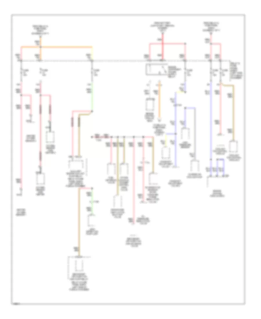
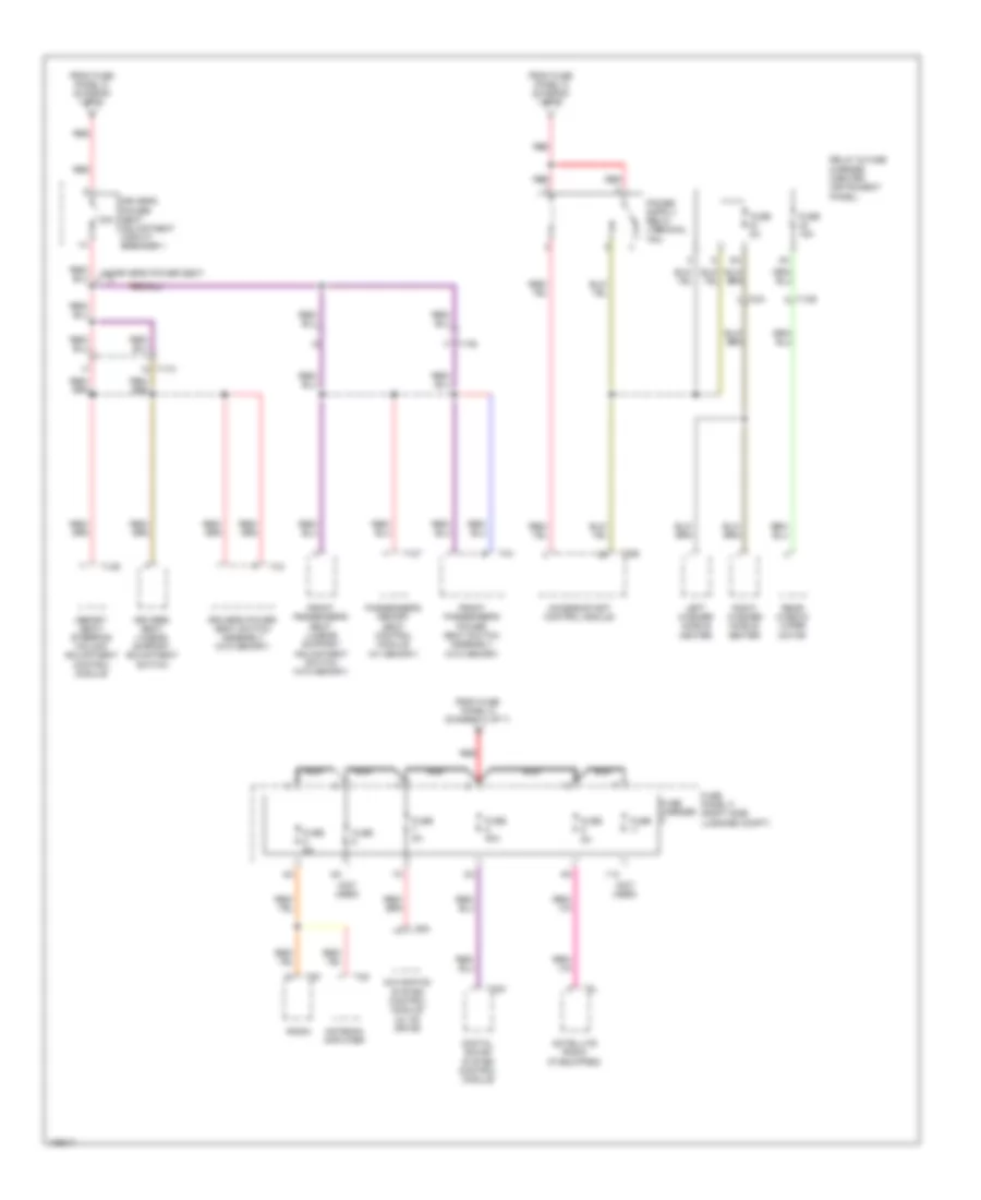
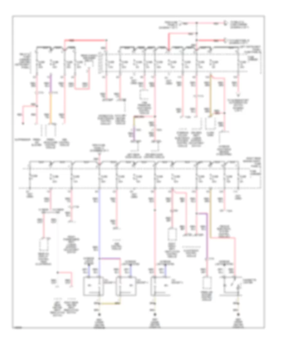
3.0L SC, Power Distribution Wiring Diagram (4 of 7) for Audi Q7 Prestige S 2013
List of elements for 3.0L SC, Power Distribution Wiring Diagram (4 of 7) for Audi Q7 Prestige S 2013:
- 10a
- 13a
- 14a
- 15a
- 19c c
- 19e
- 1b a
- 1h a
- Auxiliary engine coolant pump relay
- Camshaft adjustment valve 1
- Camshaft adjustment valve 2
- Charge air cooling pump
- Coolant fan control module
- Coolant fan control module 2
- Crankcase ventilation shut-off valve
- Engine control module (ecm)
- Evaporative emission (evap) canister purge regulator valve 1
- From battery jump start terminal (diagram 1 of 7)
- From relay & fuse panel e-box (diagram 1 of 7)
- From relay & fuse panel e-box (diagram 4 of 7)
- Fuel metering valve
- Fuse 10a
- Fuse 15a
- Fuse 5a
- Heated oxygen sensor 1
- Heated oxygen sensor 2
- High pressure sensor
- Intake manifold runner control (imrc) valve
- Leak detection pump (ldp)
- Nca
- Oil pressure regulation valve
- Oxygen sensor (o2s) heater
- Oxygen sensor (o2s) heater 2
- Red
- Relay & fuse panel e-box (left side of plenum chamber)
- Secondary air injection (air) pump relay
- Secondary air injection (air) solenoid
- T10e
- T10m
- T14l
- T94
- To relay & fuse panel e-box (diagram 4 of 7)
- Valve
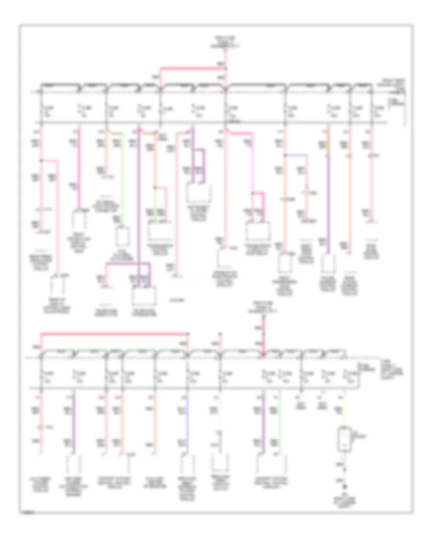
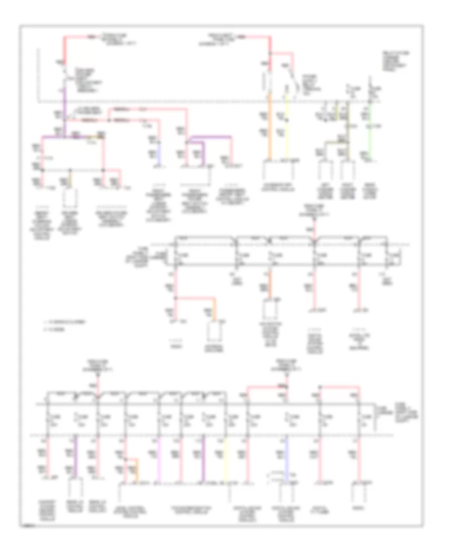
3.0L SC, Power Distribution Wiring Diagram (5 of 7) for Audi Q7 Prestige S 2013
List of elements for 3.0L SC, Power Distribution Wiring Diagram (5 of 7) for Audi Q7 Prestige S 2013:
- 10a
- 10g
- 11a
- 12a
- Access/ start control module
- Automatic dimming interior rearview mirror
- Automatic dimming interior rearview mirror relay
- Auxiliary video/audio connection module
- Brake light/ brake pedal switch
- Comfort system central control module
- Data bus on board diagnostic interface
- Data link connector
- Digital sound system control module
- Digital sound system control module 2
- Digital tv tuner
- Directional stabilization assistance control module
- Distance regulation control module
- Distance regulation sensor heater
- Engine coolant shut-off valve relay
- From fuse panel d (diagram 1 of 7)
- From relay & fuse panel g e-box (diagram 1 of 7)
- Fuse 10a
- Fuse 15a
- Fuse 20a
- Fuse 25a
- Fuse 30a
- Fuse 5a
- Fuse carrier
- Fuse carrier 3
- Fuse panel b (left instrument panel)
- Fuse panel f (right side luggage compt)
- Garage door opener control head
- Garage door opener control module
- Headlamp range control module
- Left headlamp assembly
- Level control system control module
- Light switch
- Multimedia system control module
- Nca
- Oil level thermal sensor
- Radio
- Rear lid control module
- Rear lid control module 2
- Red
- Reducing agent tank cap switch
- Steering column electronics systems control module
- T10aa
- T10f
- T10o
- T12ag
- T12c
- T12d
- T16a
- T20e
- T26e
- T2bc
- T2bd
- T32b
- T32c
- T32d
- T3ae
- T3af
- T4ai
- T81a
- T8c
- Tire pressure monitoring control module
- Towing recog- nition control module
- Towing recognition control module
- Vehicle electrical system control module
- W/ start/stop system
- W/o start/stop system
3.0L SC, Power Distribution Wiring Diagram (6 of 7) for Audi Q7 Prestige S 2013
List of elements for 3.0L SC, Power Distribution Wiring Diagram (6 of 7) for Audi Q7 Prestige S 2013:
- (not used)
- (or 7.5a)
- (right rear engine compt) fuse panel c
- (right side luggage compt) fuse panel f
- 10a
- 11a
- 12a
- 12v socket 5
- 4a (not used)
- Access/start authorization
- Access/start authorization switch
- Access/start control module
- Auxiliary heater rf recever
- Button
- Comfort system central control module
- Comfort system central control module 2
- Cooler
- Dvd player & cd changer
- External audio source connector
- From fuse k panel d (diagram 1 of 7)
- From fuse o panel b (diagram 2 of 7)
- From fuse panel d (diagram 1 of 7)
- Front information display control head
- Front information display control head control module
- Front passenger's door control module
- Fuse 10a
- Fuse 15a
- Fuse 20a
- Fuse 30a
- Fuse 35a
- Fuse 5a
- Fuse carrier
- G45 (behind center of dash)
- G51 (right side of luggage compt)
- Information electronics control module 1
- Instrument cluster control
- Instrument cluster control module
- Keyless access authorization antenna reader
- Module
- Multimedia system control module
- Nca
- Power sunroof control module
- Rear a/c display control head (climatronic)
- Rear fresh air blower control module
- Rear sliding sunroof control module
- Red
- Reducing agent metering system control module
- Reducing agent tank cap switch
- Right rear door control module
- Roof blind control module
- Selector lever sensor control module
- T10g
- T16h
- T17h
- T20b
- T20d
- T20e
- T20k
- T20m
- T20o
- T2a
- T3a
- T4ai
- T4u
- T6a
- T6y
- T8a
- T8ad
- T8af
- T8i
- Telephone base plate
- Telephone transceiver
- Transmission control module
- Transmission hydraulic pump relay
3.0L SC, Power Distribution Wiring Diagram (7 of 7) for Audi Q7 Prestige S 2013
List of elements for 3.0L SC, Power Distribution Wiring Diagram (7 of 7) for Audi Q7 Prestige S 2013:
- (not used)
- 11a
- 30a
- Access/start control module
- Antenna amplifier
- Digital sound system control module
- Driver's power seat adjustment circuit breaker 1
- Driver's power seat switch assembly (w/o memory)
- Driver's seat lumbar support adjustment switch
- From fuse panel d (diagram 1 of 7)
- Front passenger's power seat switch assembly (w/o memory)
- Front passenger's seat lumbar support adjustment switch (w/o memory)
- Fuse
- Fuse 15a
- Fuse 30a
- Fuse 5a
- Fuse carrier
- Fuse panel f (right side luggage compt)
- Left washer nozzle heater
- Memory seat/ steering column adjustment control module
- Navigation system control module (w/ cd drive)
- Nca
- Passenger's memory seat control module (w/ memory)
- Radio
- Rear window wiper motor
- Red
- Relay & fuse carrier (center instrument panel)
- Right washer nozzle heater
- Satellite radio (if equipped)
- T10r
- T12s
- T12t
- T17a
- T17b
- T20e
- T2w
- T32c
- T3q
- T4x
- T8k
- T8l
- T8n
- W/ driver's power seat
3.0L TURBO DIESEL
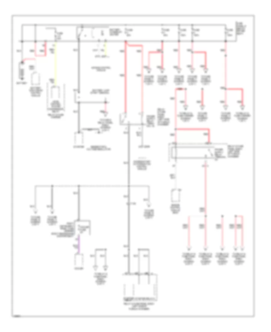
3.0L Turbo Diesel, Power Distribution Wiring Diagram (1 of 7) for Audi Q7 Prestige S 2013
List of elements for 3.0L Turbo Diesel, Power Distribution Wiring Diagram (1 of 7) for Audi Q7 Prestige S 2013:
- 2b a
- Access/start authorization control module
- Air bag control module
- Battery
- Battery interrupt igniter
- Battery jump start terminal
- Battery monitoring control module
- Cooler
- Cooler fuse 5a
- Engine control module (ecm)
- Fuse 150a
- Fuse 40a
- Fuse 50a
- Fuse 60a
- Fuse panel d (below driver seat)
- Generator & voltage regulator
- Level control system compressor relay
- Red
- Relay & fuse carrier
- Relay & fuse panel e-box (left side of plenum chamber)
- Right instrument panel fuse carrier (right rear engine compartment)
- Starter
- Starter relay
- Starter relay 2
- T10d
- T20e
- T91
- To fuse & relay panel e-box (diagram 6 of 7)
- To fuse panel b (diagram 2 of 7)
- To fuse panel b (diagram 3 of 7)
- To fuse panel c (diagram 3 of 7)
- To fuse panel c (diagram 4 of 7)
- To fuse panel c (diagram 5 of 7)
- To fuse panel f (diagram 5 of 7)
- To fuse panel f (diagram 7 of 7)
- To relay & fuse carrier (diagram 7 of 7)
- To relay & fuse panel e-box (diagram 6 of 7)
3.0L Turbo Diesel, Power Distribution Wiring Diagram (2 of 7) for Audi Q7 Prestige S 2013
List of elements for 3.0L Turbo Diesel, Power Distribution Wiring Diagram (2 of 7) for Audi Q7 Prestige S 2013:
- (left instrument panel) fuse panel b
- 10a
- 11a
- 12a
- Access/ start control module
- Access/start authorization button
- Access/start authorization switch
- Access/start control module
- Automatic dimming interior rearview mirror
- Automatic dimming interior rearview mirror relay
- Auxiliary video/ audio connection module
- Brake light/ brake pedal switch
- Comfort system central control module
- Data bus on board diagnostic interface
- Data link connector
- Directional stabilization assistance control module
- Distance regulation control module
- Distance regulation sensor heater
- Engine coolant shut-off valve relay
- From fuse panel b (diagram 3 of 7)
- From relay t & fuse panel e-box (diagram 1 of 7)
- From relay x & fuse panel e-box (diagram 1 of 7)
- Fuse 10a
- Fuse 5a
- Fuse carrier
- G45 (behind center of dash)
- Garage door opener control head
- Garage door opener control module
- Headlamp range control module
- Instrument cluster control
- Left headlamp assembly
- Light switch
- Module
- Multimedia system control module
- Nca
- Oil level thermal sensor
- Reducing agent tank cap switch
- Selector lever sensor control module
- Steering column electronic systems control module
- T10f
- T10o
- T12d
- T16a
- T20e
- T26e
- T2a
- T2bc
- T2bd
- T32b
- T32d
- T3a
- T3ae
- T3af
- T4ai
- T6a
- T8a
- T8c
- Tire pressure monitoring control module
- Towing recog- nition control module
- Vehicle electrical system control module
- W/ start/stop system w/ start/stop system
- W/o start/stop system
3.0L Turbo Diesel, Power Distribution Wiring Diagram (3 of 7) for Audi Q7 Prestige S 2013
List of elements for 3.0L Turbo Diesel, Power Distribution Wiring Diagram (3 of 7) for Audi Q7 Prestige S 2013:
- (left instrument panel) fuse panel b
- (not used)
- (right rear engine compt) fuse panel c
- 10a
- 11a
- 12a
- 12v socket 2
- 12v socket 3
- 12v socket 4
- 2a (not used)
- Abs control module
- Alarm horn
- Auxiliary heater control module
- Cigarette lighter
- Climatronic control module
- Driver's door control module
- Driver's seat lumbar support adjustment switch
- Fresh air blower
- Fresh air blower control module
- From fuse panel d (diagram 1 of 7)
- Front passenger's seat lumbar support adjustment switch
- Fuse
- Fuse 10a
- Fuse 15a
- Fuse 20a
- Fuse 25a
- Fuse 30a
- Fuse 35a
- Fuse 40a
- Fuse 5a
- Fuse 7.5a
- Fuse carrier
- G687 (under center console)
- Information electronics control module 1
- Interior lights system
- Interior monitoring sensor (if equipped)
- Left rear door module
- Left rear heated seat regulating switch
- Nca
- Rear a/c display control head (climatronic)
- Rear window defogger relay
- Red
- Relay & fuse carrier (center instrument panel)
- Right front seat ventilation control module
- Right rear heated seat regulating switch
- Steering column electronic systems control module
- Suppressor
- T16a
- T16d
- T17a
- T17b
- T17h
- T17k
- T20a
- T20c
- T20l
- T20n
- T2b
- T3c
- T3h
- T40a
- T6ai
- T6g
- T8af
- Tire pressure monitoring control module
- To access/start authorization switch (diagram 2 of 7)
- To fuse panel b (diagram 4 of 7)
- To relay & fuse carrier (diagram 4 of 7)
- Vehicle electrical system control module 2
- W/ rear a/c
- W/o rear a/c
3.0L Turbo Diesel, Power Distribution Wiring Diagram (4 of 7) for Audi Q7 Prestige S 2013
List of elements for 3.0L Turbo Diesel, Power Distribution Wiring Diagram (4 of 7) for Audi Q7 Prestige S 2013:
- (left instrument panel) fuse panel b
- (right rear engine compt) fuse panel c
- 10a
- 11a
- 12 pin connector
- 12a
- 18 pin connector
- Abs control module
- Air bag control module
- Air quality sensor
- Asr/esp button/ emergency flasher switch
- Brake booster
- Brake light disable relay
- Climatronic control module
- Data bus on board diagnostic interface
- Data link connector
- Dual tone horn relay
- From fuse panel b (diagram 3 of 7)
- From fuse r panel b (diagram 3 of 7)
- From relay & fuse panel e-box (diagram 1 of 7)
- Front pass- enger's air bag disabled indicator lamp
- Fuse 10a
- Fuse 15a
- Fuse 25a
- Fuse 30a
- Fuse 5a
- Fuse carrier
- Headlamp washer relay (if equipped)
- Lane change assis- tance control module
- Lane change assis- tance control module 2
- Left front seat ventilation control module
- Left rear heated seat regul- ating switch
- Level control system control module
- Multi- function transmission range (tr) switch
- Nca
- Parking aid control module
- Peripheral camera control module
- Rain/light recognition sensor
- Rear a/c display control head (w/ climatronic display & control head)
- Red
- Relay & fuse carrier (center instrument panel)
- Relay & fuse carrier under driver seat (below driver seat)
- Right headlamp assembly
- Right rear heated seat regul- ating switch
- Seat occupied recognition control module
- Selector lever sensor system control module
- T10a
- T12b
- T12z
- T14d
- T14h
- T16b
- T16d
- T16h
- T17b
- T18
- T18e
- T4y
- T6f
- T81a
- Transmission control module (tcm)
- Vehicle electrical system control module
- Vehicle positioning system fuse 5a
- Wiper motor control module
3.0L Turbo Diesel, Power Distribution Wiring Diagram (5 of 7) for Audi Q7 Prestige S 2013
List of elements for 3.0L Turbo Diesel, Power Distribution Wiring Diagram (5 of 7) for Audi Q7 Prestige S 2013:
- (not used)
- (or 5a)
- (right rear engine compt) fuse panel c
- 10a
- 11a
- 12a
- 12v socket
- Auxiliary heater rf recever
- Comfort system central control module
- Comfort system central control module 2
- Cooler
- Dvd player & cd changer
- External audio source connector
- From fuse panel d (diagram 1 of 7)
- Front information display control head
- Front passenger's door control module
- Fuse
- Fuse 10a
- Fuse 15a
- Fuse 20a
- Fuse 30a
- Fuse 35a
- Fuse 5a
- Fuse 7.5a
- Fuse carrier
- Fuse panel f (right side of luggage compt)
- G51 (right side of luggage compt)
- Information electronics control module 1
- Instrument cluster control module
- Keyless access authorization antenna reader
- Multimedia system control module
- Nca
- Power sunroof control module
- Rear a/c display control head (climatronic)
- Rear fresh air blower control module
- Rear sliding sunroof control module
- Red
- Reducing agent metering system control module
- Reducing agent tank cap switch
- Right rear door control module
- Roof blind control module
- T10g
- T16h
- T17h
- T20b
- T20d
- T20m
- T2o0
- T4ai
- T4u
- T6y
- T8ad
- T8af
- T8i
- Telephone base plate
- Telephone transceiver
- Transmission control module
- Transmission hydraulic pump relay
3.0L Turbo Diesel, Power Distribution Wiring Diagram (6 of 7) for Audi Q7 Prestige S 2013
List of elements for 3.0L Turbo Diesel, Power Distribution Wiring Diagram (6 of 7) for Audi Q7 Prestige S 2013:
- 10a
- 11a
- 12a
- 13a
- 14a
- 15a
- 16a
- 17a
- 18a
- 1d b
- 4c b
- 8al
- Automatic glow time control module
- B 1b
- B 3a
- B 3c
- B 4a
- Coolant circulation pump relay
- Coolant fan control (fc) control module
- Coolant fan control module
- Coolant fan control module 2
- Cylinder head coolant valve
- Electro hydraulic engine mount solenoid valve
- Engine control module (ecm)
- Exhaust gas recirculation (egr) cooler switch-over valve
- From battery jump start terminal (diagram 1 of 7)
- From relay & fuse panel e-box (diagram 1 of 7)
- Fuel metering valve
- Fuel pressure regulator valve
- Fuel pump control module
- Fuse 10a
- Fuse 15a
- Fuse 20a (or 25a)
- Fuse 40a
- Fuse 5a
- Fuse 60a
- Fuse 80a
- Heat setting relay 3
- High heat output relay
- High pressure sensor
- Low heat output relay
- Map controlled engine cooling thermostat
- Mass air flow (maf) sensor
- Nca
- Nox sensor control module
- Nox sensor control module 2
- Oil pressure regulation valve
- Oxygen sensor (o2s) heater
- Particulate sensor
- Red
- Reducing agent pump
- Relay & fuse carrier (center instrument panel)
- Relay & fuse panel e-box (left side of plenum chamber)
- T10ab
- T10d
- T10e
- T10m
- T17e
- T91
3.0L Turbo Diesel, Power Distribution Wiring Diagram (7 of 7) for Audi Q7 Prestige S 2013
List of elements for 3.0L Turbo Diesel, Power Distribution Wiring Diagram (7 of 7) for Audi Q7 Prestige S 2013:
- (diagram 1 of 7)
- (not used)
- 10a
- 10g
- 11a
- 12a
- 30a
- Access/start control module
- Antenna amplifier
- Comfort system central control module
- Digital sound system control module
- Digital sound system control module 2
- Digital tv tuner
- Driver's power seat adjustment circuit breaker 1
- Driver's power seat switch assembly (w/o memory)
- Driver's seat lumbar support adjustment switch
- From fuse panel d (diagram 1 of 7)
- From fuse panel d w
- Front passenger's power seat switch assembly (w/o memory)
- Front passenger's seat lumbar support adjustment switch (w/o memory)
- Fuse 15a
- Fuse 20a
- Fuse 25a
- Fuse 30a
- Fuse 5a
- Fuse carrier
- Fuse panel f (right side of luggage compt)
- Left washer nozzle heater
- Level control system control module
- Memory seat/ steering column adjustment control module
- Navigation system control module w/ cd drive
- Nca
- Passenger's memory seat control module (w/ memory)
- Radio
- Rear lid control module
- Rear lid control module 2
- Rear window wiper motor
- Red
- Relay & fuse carrier (center instrument panel)
- Right washer nozzle heater
- Satellite radio (if equipped)
- T10aa
- T10r
- T12ag
- T12c
- T12d
- T12s
- T12t
- T17a
- T17b
- T20e
- T2w
- T32c
- T38
- T3q
- T4x
- T81a
- T8k
- T8l
- T8n
- Towing recognition control module
- W/ bang & olufsen
- W/ bose
- W/ driver's power seat

 Čeština
 Dansk
Dansk Deutsch
 Ελληνικά
 English
 English
 Español
 Suomi
Suomi Français
 Français
 עברית
עברית Hrvatski
 Magyar
 日本語
日本語 한국어
한국어 Nederlands
 Polski
 Português
 Português
 Română
 Русский
 Slovenčina
 Slovenščina
 Svenska
 Türkçe
 中文 (中国)