GROUND DISTRIBUTION
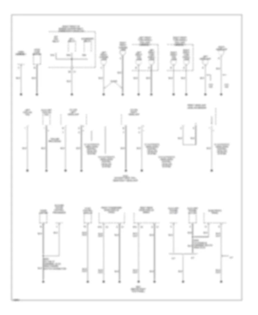
Ground Distribution Wiring Diagram (1 of 5) for Cadillac CTS 2004
 https://portal-diagnostov.com/license.html
Automotive Electricians Portal FZCO
Automotive Electricians Portal FZCO
https://portal-diagnostov.com/license.html
https://portal-diagnostov.com/license.html
Automotive Electricians Portal FZCO
Automotive Electricians Portal FZCO
List of elements for Ground Distribution Wiring Diagram (1 of 5) for Cadillac CTS 2004:
- (3.2l left rear of engine) g107
- (3.2l, 3.6l): right side of engine compartment) (5.7l): on inner fender wall, near battery) g105
- (3.6l: back of right cylinder head) (5.7l: on engine block, near generator) (3.2l: on engine block, near starter) g102
- (in cellular antenna coax cable, about 31 cm from g304) s309
- (on right
- (on right frame rail, near abs module) g110
- (on the rear package shelf, left of subwoofer) g304
- (under center console) g306
- A/c compressor clutch
- A/t
- After boil coolant pump
- Automatic transmission
- B12
- Back-up switch
- Battery
- Brake fluid level switch
- Cellular antenna
- Coolant bypass valve solenoid
- Coolant level switch
- Dash integration module (dim)
- Electronic brake control module (ebcm)
- Engine control module (ecm)
- G100 (3.2l: left rear side of engine)
- G101 (near left front strut tower)
- Headlamp washer fluid pump
- If equipped
- Ignition coil bank 1
- Ignition coil bank 2
- Inflatable restraint sensing & diagnostic module (sdm)
- Left heated washer nozzle
- M/t
- Nca
- Rear window defogger
- Right heated washer nozzle
- Transmission control module (tcm)
- Vehicle communication interface module (vcim)
- Vehicle speed sensor (vss)
- W/ high pressure headlamp washer
- W/o high pressure headlamp washer
- Washer fluid level switch
- Windshield washer fluid pump
- Windshield wiper/ washer module
- ``c" pillar) g303
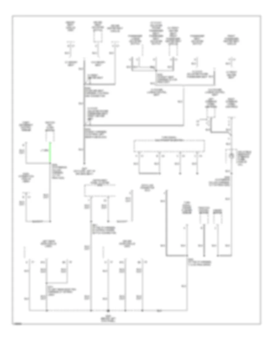
Ground Distribution Wiring Diagram (2 of 5) for Cadillac CTS 2004
List of elements for Ground Distribution Wiring Diagram (2 of 5) for Cadillac CTS 2004:
- (right front of engine compartment) underhood fuse block
- (w/ hid) left headlamp
- (w/ hid) right headlamp
- A/t
- Accessory relay
- Auxiliary cooling fan
- Auxiliary power outlet
- B12
- Blower motor control processor
- Cigar lighter
- Electronic prndl
- From c312)
- Front headlamp leveling sensor
- Front passenger door module (fpdm)
- G104 (on right body rail, near right headlamp)
- G201 (behind right kick panel)
- Hood ajar switch
- Horn assembly
- Hvac control module
- Ign 1 relay
- Left cooling fan
- Left front fog lamp
- Left front marker lamp
- Left front turn signal lamp
- Left front turn signal/ fog lamp assembly
- Left headlamp
- M/t
- R16
- R35
- R46
- Right front fog lamp
- Right front marker lamp
- Right front turn signal lamp
- Right front turn signal/ fog lamp assembly
- Right headlamp
- Right rear door module (rrdm)
- S/p fan relay
- S202 (in the i/p harness, 48 cm from hazard switch connector)
- Trailer provisions
- W/ automatic headlamps control leveling system
- W/ hid
- W/o automatic headlamps control leveling system
- W/o hid
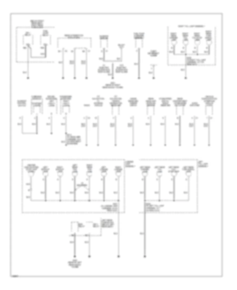
Ground Distribution Wiring Diagram (3 of 5) for Cadillac CTS 2004
List of elements for Ground Distribution Wiring Diagram (3 of 5) for Cadillac CTS 2004:
- (w/ 8-way adjuster power passenger seat) passenger seat adjuster switch
- (w/ front heater seat) front passenger heated seat module
- B12
- Dash integration module (dim)
- Data link connector (dlc)
- Driver door module (ddm)
- Driver heated seat module
- Driver seat adjuster switch
- Front passenger heated seat module
- G200 (behind left kick panel)
- G307 (on floor, left of driver's seat)
- Hazard switch
- Ignition key alarm switch
- Inflatable restraint steering wheel module coil
- Instrument panel cluster (ipc)
- Left rear door module (lrdm)
- Left steering wheel controls
- Memory seat module (msm)
- Passenger lumbar adjuster switch
- Passenger seat adjuster switch
- Right steering wheel controls
- S200 (in the i/p harness, 11.5 cm from sp200)
- S201 (in the i/p harness, 54 cm from hazard switch connector)
- S205 (in steering column harness, 12.7 cm from c202)
- S208 (in steering column harness, 12.7 cm from c202)
- S305 (in body harness, 18 cm from left rear fuse block)
- S350 (in driver seat harness, 8 cm from msm connector)
- Theft deterrent control module
- Traction control switch
- Turn signal/ hazard flasher module
- Turn signal/ multi-function switch
- W/ 8-way adjuster power passenger seat
- W/ 8-way adjuster power passenger seat, front heater seat
- W/ front heater seat
- W/ memory seat
- W/ power lumbar control seat
- W/o memory seat
- W/o power lumbar control seat
Ground Distribution Wiring Diagram (4 of 5) for Cadillac CTS 2004
List of elements for Ground Distribution Wiring Diagram (4 of 5) for Cadillac CTS 2004:
- (below right rear seat) right rear fuse block
- (if equipped)
- (if equipped) digital radio receiver
- (w/ navigation) traffic information receiver
- (w/ navigation) tv antenna module
- Audio amplifier
- B11
- Bas relay
- Center high mounted stop lamp (chmsl)
- Coil
- Courtesy lamps
- Driver sunshade
- Fuel pump & sender assembly
- Fuel pump relay
- G401 (rear of right rear shock tower)
- G402 (rear of left rear shock tower)
- Ign 1 relay
- Ign 3 relay
- Inside rearview mirror (isrvm)
- Left backup lamp
- Left license lamp
- Left rear fog lamp
- Left rear fuse block (below left rear seat)
- Left rear marker lamp
- Left rear tail lamp
- Left rear tail/ stop lamp
- Left rear turn signal lamp
- Left tail lamp assembly
- Left vanity lamps
- License lamp assembly
- Nca
- Overhead console
- Passenger sunshade
- R21
- R25
- R36
- Radio
- Rear compartment lid release actuator
- Rear headlamp leveling sensor
- Rear integration module (rim)
- Right backup lamp
- Right license lamp
- Right rear fog lamp
- Right rear marker lamp
- Right rear tail lamp
- Right rear tail/stop lamp
- Right rear turn signal lamp
- Right tail lamp assembly
- Right vanity lamps
- S401 (in license lamp harness, 40 cm from c421)
- S405 (in left tail lamp harness, 12.7 cm from c410)
- S406 (in right tail lamp harness, 12.7 cm from c411)
- Sunroof control switch
- Sunroof module
- Sunshade)
- Theft deterrent alarm
- Vehicle communication interface module (vcim)
- W/ electric sliding sun roof glass
- W/o electric sliding sun roof glass
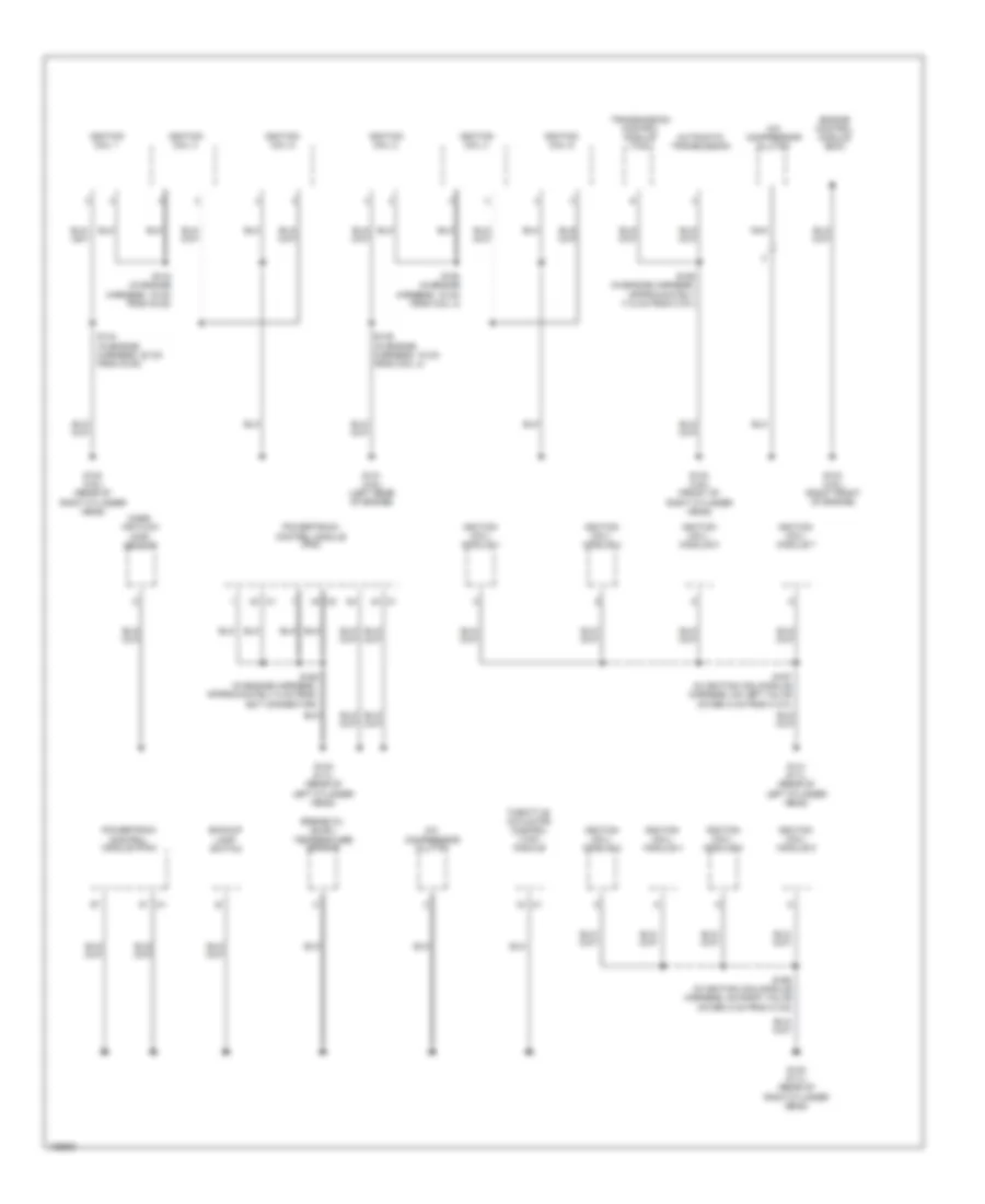
Ground Distribution Wiring Diagram (5 of 5) for Cadillac CTS 2004
List of elements for Ground Distribution Wiring Diagram (5 of 5) for Cadillac CTS 2004:
- A/c compressor clutch
- Automatic transmission
- Backup lamp switch
- Engine control module (ecm)
- Engine oil level/ temperature sensor
- G130 (3.6l) (rear of right cylinder head)
- G131 (3.6l) (left rear of engine)
- G132 (3.6l) (front of right cylinder head)
- G133 (3.6l) (right front of engine)
- G140 (5.7l) (rear of left cylinder head)
- G141 (5.7l) (rear of left cylinder head)
- G142 (5.7l) (rear of right cylinder head)
- Ignition coil 1
- Ignition coil 2
- Ignition coil 3
- Ignition coil 4
- Ignition coil 5
- Ignition coil 6
- Ignition coil/ module 1
- Ignition coil/ module 2
- Ignition coil/ module 3
- Ignition coil/ module 4
- Ignition coil/ module 5
- Ignition coil/ module 6
- Ignition coil/ module 7
- Ignition coil/ module 8
- Mass air flow (maf) sensor
- Nca
- Powertraiin control module (pcm)
- Powertrain control module (pcm)
- S143 (in engine harness, 15 cm from g130)
- S144 (in engine harness, 20 cm from g130)
- S149 (in engine harness, 15 cm from coil 4)
- S150 (in engine harness, 15 cm from coil 4)
- S155 (in engine harness, approximately 17.5 cm from c101)
- S160 (in engine harness, approximately 8 cm from ect connector)
- S167 (in ignition coil/module harness, on left valve cover, 5 cm from c131)
- S168 (in ignition coil/module harness, on right valve cover, 5 cm from c132)
- Throttle actuator control (tac) module
- Transmission control module (tcm)

 Čeština
 Dansk
Dansk Deutsch
 Ελληνικά
 English
 English
 Español
 Suomi
Suomi Français
 Français
 עברית
עברית Hrvatski
 Magyar
 日本語
日本語 한국어
한국어 Nederlands
 Polski
 Português
 Português
 Română
 Русский
 Slovenčina
 Slovenščina
 Svenska
 Türkçe
 中文 (中国)