ENGINE PERFORMANCE
2.4L
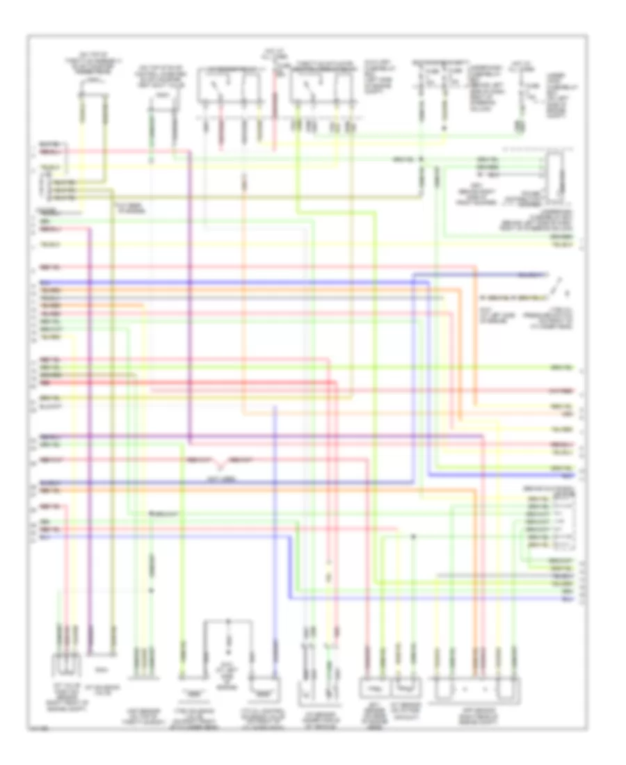
2.4L, Engine Performance Wiring Diagram (1 of 4) for Honda CR-V EX 2005
 https://portal-diagnostov.com/license.html
Automotive Electricians Portal FZCO
Automotive Electricians Portal FZCO
https://portal-diagnostov.com/license.html
https://portal-diagnostov.com/license.html
Automotive Electricians Portal FZCO
Automotive Electricians Portal FZCO
List of elements for 2.4L, Engine Performance Wiring Diagram (1 of 4) for Honda CR-V EX 2005:
- (a/t)
- (at left side of engine) g101
- (at top of engine)
- (behind glove box)
- (behind glove box) j/c c105
- (behind left side of dash, right of steering column) under-dash fuse/relay box
- (behind right side of dash)
- (m/t)
- (middle of engine)
- (on rear of cylinder head) cmp sensor a
- (top of fuel tank) fuel tank unit
- A10
- A11
- A12
- A13
- A14
- A15
- A16
- A17 a18
- A19
- A20
- A21
- A22
- A23
- A24
- A25
- A26
- A27
- A28
- A29
- A30
- A31
- Afs (+)
- Afs (-)
- Afshtc
- All times
- Altc
- Altf
- Altl
- Apsa
- Apsb
- Auxiliary fuse/relay box (left side of engine compt)
- B10
- B11
- B12
- B13
- B14
- B15
- B16
- B17
- B18
- B19
- B20
- B21
- B22
- B23
- B24
- Barometer sensor
- Ckp
- Ckp sensor (on lower left front of engine, near crankshaft pulley)
- Cmp sensor b (on rear of cylinder head)
- Cmpa
- Cmpb
- Cruise control system
- D10
- D11
- D12
- D13
- D14
- D15
- D16
- D17
- Dbwrly
- Ecm/pcm (behind right side of dash)
- Ect
- Fuel injectors
- Fuel pump
- Fuse 15a
- G101
- G101 (middle of engine)
- G551 (under driver's seat)
- Hot at
- Iat
- Icm
- Ignition coil 1
- Ignition coil 2
- Ignition coil 3
- Ignition coil 4
- Ignition coil relay
- Igp1
- Igp2
- Igpls1
- Igpls2
- Igpls3
- Igpls4
- Imt
- Imtvps
- Inj1
- Inj2
- Inj3
- Inj4
- J/c c103 (at rear of engine)
- Lg1
- Lg2
- Map
- Pcs
- Pg1
- Pg2
- Pgm-f1 main relay 1
- Pgm-f1 main relay 2
- Red
- Sedf
- Sefd
- Setind
- Sg1
- Sg2
- Starting/ charging system
- Vcc1
- Vcc2
- Vss(m/t) nc (a/t)
- Vtc
- Vtpsw
- Vts
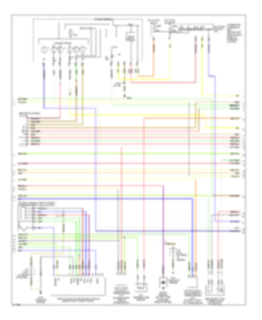
2.4L, Engine Performance Wiring Diagram (2 of 4) for Honda CR-V EX 2005
List of elements for 2.4L, Engine Performance Wiring Diagram (2 of 4) for Honda CR-V EX 2005:
- (at rear of engine)
- (behind glove box) j/c c105
- (not used)
- (on top of evap control canister) evap canister vent shut valve
- (on top of throttle assembly) evap canister purge valve
- A/f sensor (under middle of vehicle)
- A/f sensor relay
- Air duct)
- App sensor (right rear of engine compt)
- Auxiliary fuse/relay box (left side of engine compt)
- C10
- Ect sensor (on rear of engine head)
- Eld unit
- Fuse 10a
- Fuse 20a
- Fuse 7.5a
- G101 (at left side of engine)
- G201 (behind right side of front bumper)
- Hot at all times
- Hot in on or start
- Iat sensor (on intake
- Imt solenoid valve
- Imt valve position sensor (right front of engine compt)
- Map sensor (on top of throttle body)
- Power distribution system
- Red
- Throttle actuator control module relay
- Under- hood fuse/relay box (on left side of engine compt)
- Under-dash fuse/relay box (behind left side of dash, right of steering column)
- Vtc oil control solenoid valve (on front of cylinder head)
- Vtec oil pressure switch (on front of cylinder head)
- Vtec solenoid valve (on right front of cylinder head)
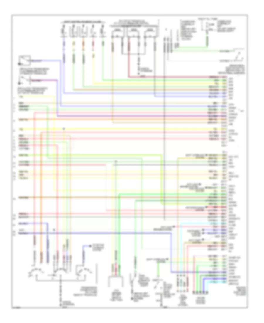
2.4L, Engine Performance Wiring Diagram (3 of 4) for Honda CR-V EX 2005
List of elements for 2.4L, Engine Performance Wiring Diagram (3 of 4) for Honda CR-V EX 2005:
- (behind glove box)
- (on right side of throttle body.) tp/sensor/throttle actuator
- A13
- A14
- A15
- A16
- A18
- Acc radio
- Atf temperature sensor
- Atp-p
- B20
- Bus (ecu)
- Bus meter
- Cpu
- Dbw m+
- Dbwm-
- Dimming circuit
- Drive circuit
- E10
- Fuse 7.5a
- G101 (middle of engine)
- G502
- Gauge assembly
- Hot in acc or on
- Hot in on or start
- Ig1 meter
- Input shaft (mainshaft) speed sensor (a/t) (on rear right side of transmission)
- J/c c103 (at rear of engine)
- J/c c105
- K10
- Knock sensor (on left side of engine, near starter)
- Mil ind
- Multiplex control unit
- Output shaft (countershaft) speed sensor (a/t) (on front right of transmission)
- Pg2
- Secondary ho2s (under middle of vehicle)
- Sedf
- Sefd
- Thl1
- Thl2
- Throttle actuator control module (behind right side of dash)
- Under-dash fuse/relay box (behind left side of dash, right of steering column)
- Usa: ex, se
- Vcc
2.4L, Engine Performance Wiring Diagram (4 of 4) for Honda CR-V EX 2005
List of elements for 2.4L, Engine Performance Wiring Diagram (4 of 4) for Honda CR-V EX 2005:
- anti-lock brakes system
- (a/t)
- (behind left side of front bumper) g301
- (middle of engine)
- (middle of engine) g101
- (on top of transaxle) a/t clutch pressure control solenoid valves
- 2nd clutch transmission fluid pressure switch (at top of transaxle)
- 3rd clutch transmission fluid pressure switch (at rear of transaxle)
- A/t
- Acc
- Afshtcr
- Air conditioning system
- Anti-lock brakes system
- Anti-theft system
- Atft
- Atp1
- Atp2
- Atpd
- Atpfwd
- Atpn
- Atpp
- Atpr
- Atprvs
- Bksw
- Bkswnc
- Brake pedal position switch (behind dash, on brake pedal support)
- C10
- C11
- C12
- C13
- C14
- C15
- C16
- C17
- C18
- C19
- C20
- C21
- C22
- Can h
- Can l
- Cooling fans system
- Cr res sw
- Cr set sw
- Crmsw
- Crmtcls
- Cruise control system
- D3 switch (on end of a/t gear selector lever)
- D3sw
- Dlc (under left side of dash)
- E10
- E11
- E12
- E13
- E14
- E15
- E16
- E17
- E18
- E19
- E20
- E21
- E22
- E23
- E24
- E25
- E26
- E27
- E28
- E29
- E30
- E31
- Ecm/pcm (behind right side of dash)
- Eld
- Fanc
- Ftp
- Ftp sensor (on left rear of fuel tank)
- Fuse 15a
- G101
- G451
- Hot at all times
- Ig1
- Imo fpr
- Imocd
- Instrument cluster system
- K-line
- Lg3
- Lsa
- Lsb
- Lsc
- Mil
- Mrly
- Nep
- O12
- Op2sw
- Op3sw
- P-pin sw
- Pnk
- Psp switch (rear of engine compt)
- Pspsw
- Red
- Scs
- Sefmj
- Sg3
- Sha
- Shb
- Shc
- Shd
- She
- Shift control solenoid valves
- Shift interlock system
- Sho2s
- Sho2shtc
- Sls
- Starting/ charging system
- Transmission range switch (on lower rear of transaxle)
- Under-dash fuse/relay box (behind left side of dash, right of steering column)
- Under-hood fuse/relay box (on left side of engine compt)
- Vcc3
- Vssout
- Vsv
- Wen

 Čeština
 Dansk
Dansk Deutsch
 Ελληνικά
 English
 English
 Español
 Suomi
Suomi Français
 Français
 עברית
עברית Hrvatski
 Magyar
 日本語
日本語 한국어
한국어 Nederlands
 Polski
 Português
 Português
 Română
 Русский
 Slovenčina
 Slovenščina
 Svenska
 Türkçe
 中文 (中国)