ENGINE PERFORMANCE
2.3L
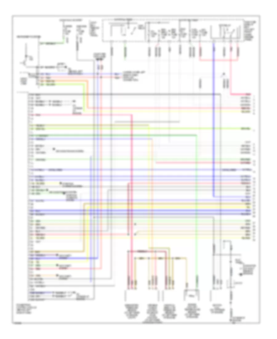
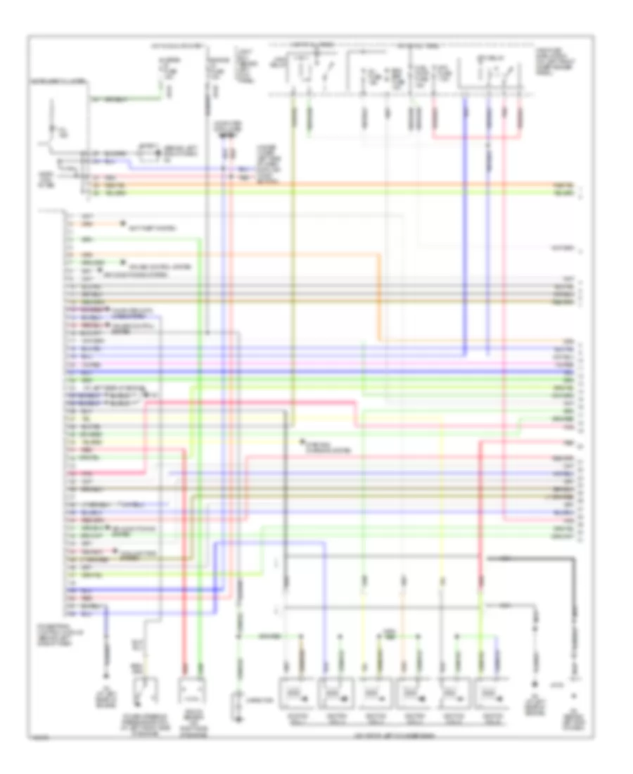
2.3L, Engine Performance Wiring Diagram (1 of 4) for Mazda 6 i 2004
List of elements for 2.3L, Engine Performance Wiring Diagram (1 of 4) for Mazda 6 i 2004:
- (under lower left side of dash) data link connector 2
- 1aa
- 1ab
- 1ac
- 1ad
- 2aa
- 2ab
- 2ac
- 2ad
- Air conditioning system
- Anti-theft system
- Barometric pressure sensor (at left rear of engine compt)
- Capacitor (at right rear of engine)
- Computer data lines system
- Eng b + fuse 7.5a
- Eng bar 2 fuse 15a
- Eng bar fuse 10a
- Engine coolant temperature sensor (at left rear of engine)
- Engine ig fuse 15a
- Engine) g3
- Etc fuse 7.5a
- Etc relay
- Fuel pump fuse 15a
- G2 (behind left end of dash)
- G3 (at rear of engine)
- Hot at all times
- Hot in run or start
- Ignition coil (on top rear of engine)
- Inj fuse 15a
- Instrument cluster
- J/c-02
- J/c-x13
- Jb-01
- Jb-02
- Joint box (behind left kick panel)
- Main fuse & relay box (on left front inner fender panel)
- Main relay
- Manifold absolute pressure sensor (at left rear of engine)
- Meter ig fuse 15a
- Micro comp- uter
- Mil ind
- Nca
- Pnk
- Powertrain control module (behind left side of dash)
- Red
- Starting/ charging system
- Variable tumble control solenoid valve monitor (at left rear of engine compt)
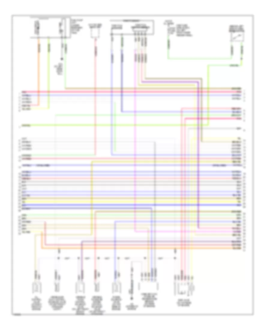
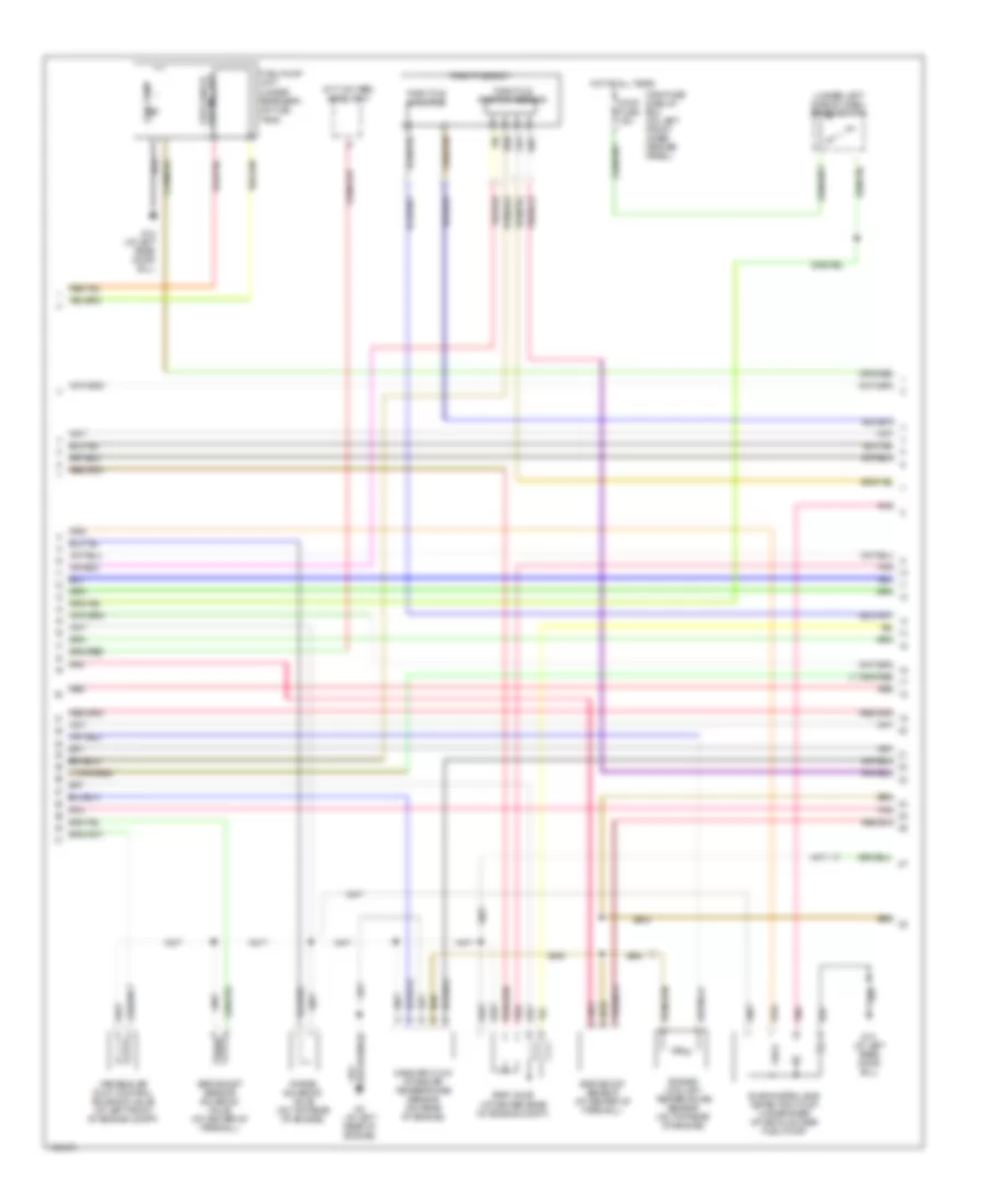
2.3L, Engine Performance Wiring Diagram (2 of 4) for Mazda 6 i 2004
List of elements for 2.3L, Engine Performance Wiring Diagram (2 of 4) for Mazda 6 i 2004:
- (behind left side of dash) brake switch
- (m/t w/o abs) audio unit
- Egr valve (on top rear of engine)
- Fuel gauge sending unit
- Fuel pump
- Fuel pump unit (under rear seat, on fuel tank)
- G13 (at left rear door sill)
- G3 (at rear of engine)
- Hot at all times
- Main fuse & relay box (on left front inner fender panel)
- Mass air flow/ intake air temperature sensor (on rear of engine)
- Oil control valve (at right front of engine)
- Pnk
- Purge solenoid valve (on top rear of engine)
- Stop fuse 15a
- Throttle actuator
- Throttle body
- Throttle position sensor
- Variable air duct control solenoid valve (at left front of engine compt)
- Variable intake-air system control solenoid valve (at left front of engine)
- Variable timing control solenoid valve (on left front side of engine)
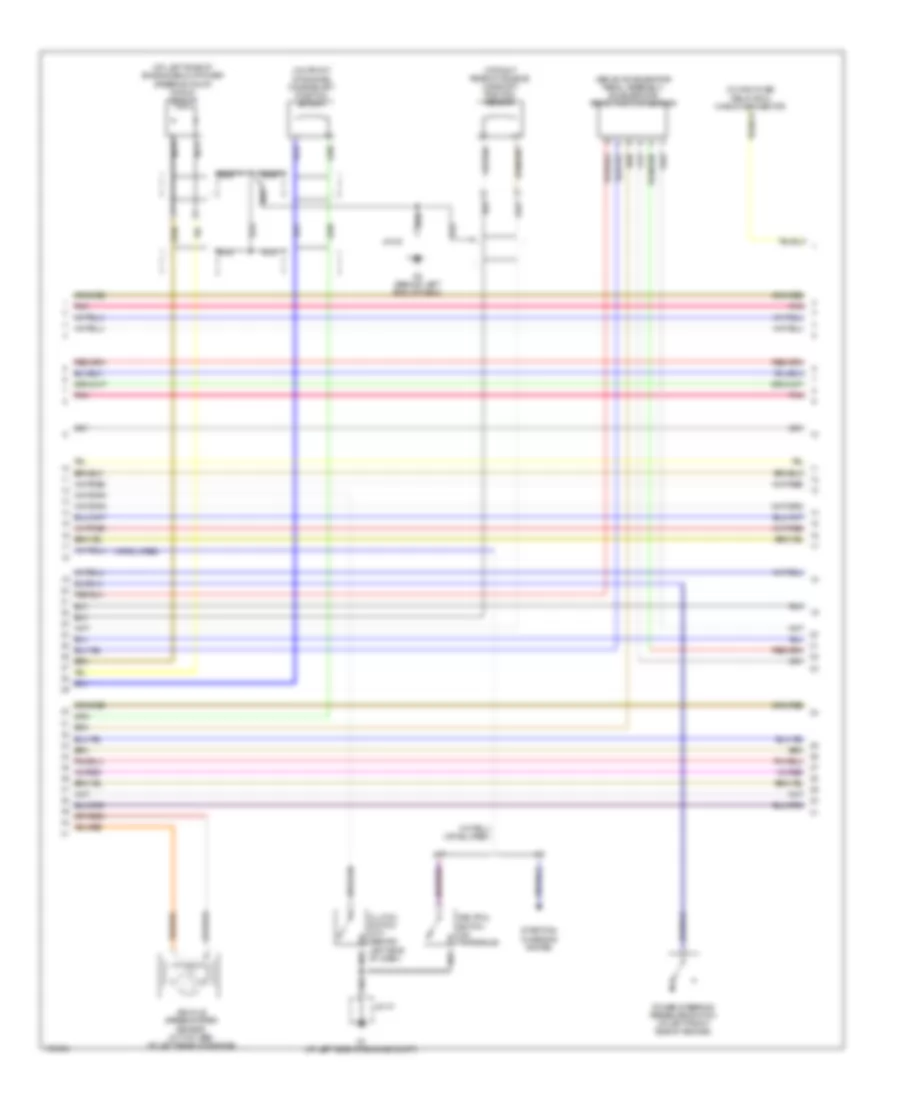
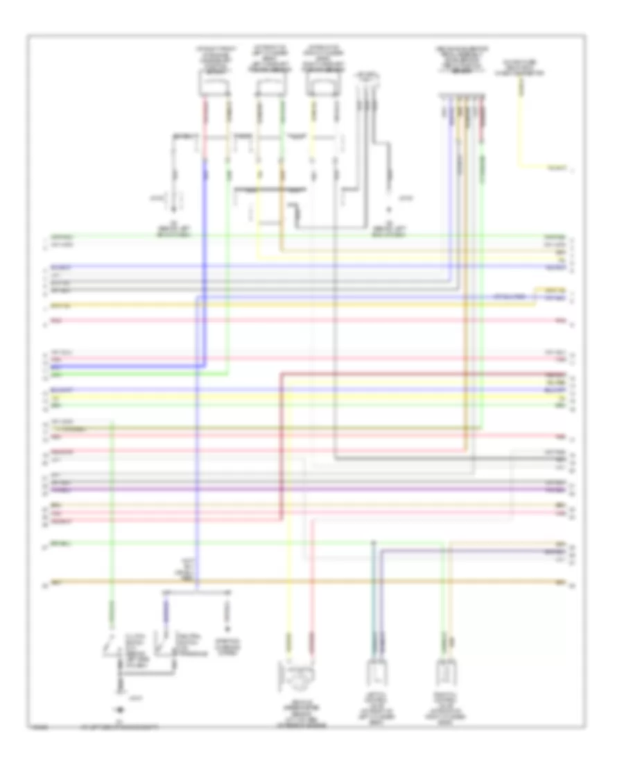
2.3L, Engine Performance Wiring Diagram (3 of 4) for Mazda 6 i 2004
List of elements for 2.3L, Engine Performance Wiring Diagram (3 of 4) for Mazda 6 i 2004:
- (above accelerator pedal assembly) accelerator pedal position sensor
- (at right rear of engine) camshaft position sensor
- (in main fuse/ relay box) check connector
- (on front of engine) crankshaft position sensor
- (on left side of engine, below power steering pump) knock sensor
- A/t
- Clutch switch (m/t) (behind left side of dash)
- G1 (at left side of engine compt)
- G2 (behind left end of dash)
- J/c-01
- J/c-02
- M/t
- Nca
- Neutral switch (on transaxle)
- Pnk
- Power steering pressure switch (at left front side of engine)
- Starting/ charging system
- Vehicle speedometer sensor (m/t w/o abs) (at left rear of engine)
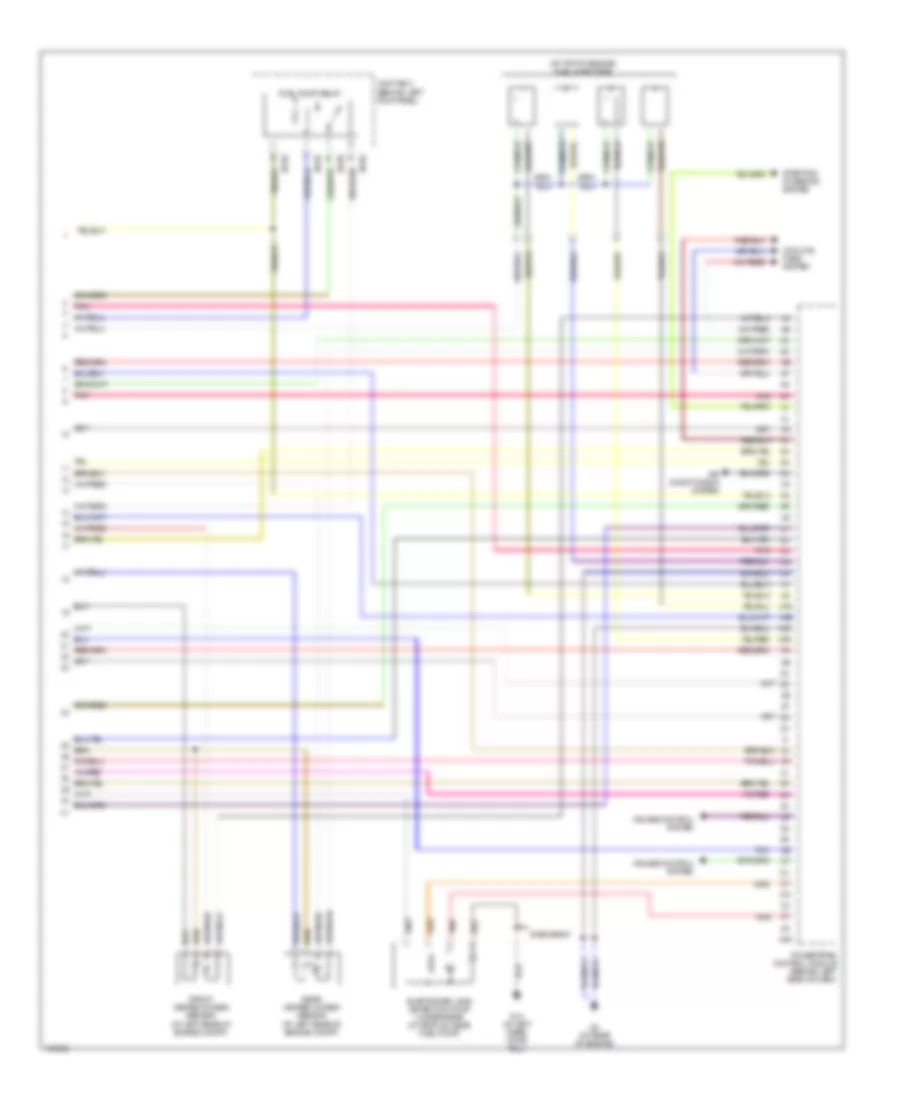
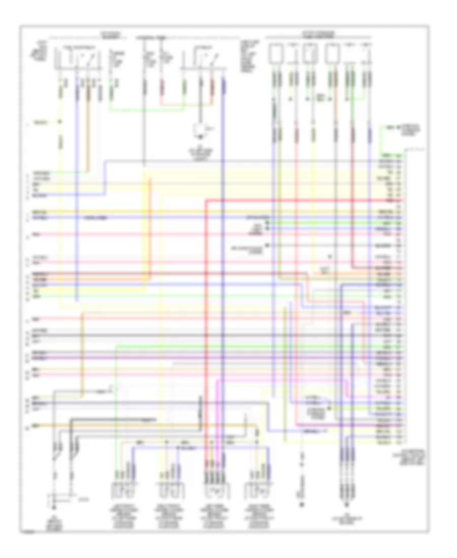
2.3L, Engine Performance Wiring Diagram (4 of 4) for Mazda 6 i 2004
List of elements for 2.3L, Engine Performance Wiring Diagram (4 of 4) for Mazda 6 i 2004:
- (at top of engine) fuel injectors
- 3aa
- 4aa
- 4ab
- 4ac
- 4ad
- 5hb/wagon
- Air conditioning system
- Cooling fans system
- Cruise control system
- Evap system leak detection pump (under rear of vehicle, near fuel pump)
- Front heated oxygen sensor (at left rear of engine compt)
- Fuel pump relay
- G13 (at left rear door sill)
- G3 (at rear of engine)
- Jb-02
- Jb-05
- Joint box (behind left kick panel)
- Pnk
- Powertrain control module (behind left side of dash)
- Rear heated oxygen sensor (at left rear of engine compt)
- Starting/ charging system
3.0L
3.0L, Engine Performance Wiring Diagram (1 of 4) for Mazda 6 i 2004
List of elements for 3.0L, Engine Performance Wiring Diagram (1 of 4) for Mazda 6 i 2004:
- (at left rear of engine)
- (behind left end of dash) g2
- (on top of left cylinder bank)
- (under lower left side of dash) data link conn- ector 2
- Air conditioning system
- Anti-theft system
- Capacitor
- Computer data lines system
- Cooling fans system
- Cruise control system
- Eng bar fuse 15a
- Engine ig fuse 15a
- Etc fuse 7.5a
- Etc relay
- Fuel pump fuse 15a
- G2 (behind left end of dash)
- G3 (at left rear of engine)
- Hot at all times
- Hot in run or start
- Ignition coil 1
- Ignition coil 2
- Ignition coil 3
- Ignition coil 4
- Ignition coil 5
- Ignition coil 6
- Inj fuse 15a
- Instrument cluster
- J/c 02
- J/c-02
- Jb-01
- Jb-02
- Joint box (behind left kick panel)
- Knock sensor (on right side of engine)
- Main fuse & relay box (on left front inner fender panel)
- Main relay
- Meter ig fuse 15a
- Micro com- puter
- Mil ind
- Nca
- Pnk
- Power steering pressure switch (at left front side of engine)
- Powertrain control module (behind left side of dash)
- Red
- Starting/ charging system
3.0L, Engine Performance Wiring Diagram (2 of 4) for Mazda 6 i 2004
List of elements for 3.0L, Engine Performance Wiring Diagram (2 of 4) for Mazda 6 i 2004:
- (m/t, w/o abs) audio unit
- (under left side of dash) brake switch
- Egr boost sensor (at center of firewall)
- Egr boost sensor solenoid valve (at center of firewall)
- Egr valve (at center rear of engine compt)
- Engine coolant temperature sensor (on top rear of engine)
- Evap system leak detection pump (under rear of vehicle, near fuel pump)
- Fuel gauge sending unit
- Fuel pump
- Fuel pump unit (under rear seat, on fuel tank)
- G13 (at left rear door sill)
- G3 (at left rear of engine)
- Hot at all times
- Main fuse & relay box (on left front inner fender panel)
- Mass air flow/ intake air temperature sensor (on rear of engine)
- Pnk
- Pnk a
- Purge solenoid valve (on top rear of engine)
- Red
- Stop fuse 15a
- Throttle actuator
- Throttle body
- Throttle position sensor
- Variable air duct control solenoid valve (at left front of engine compt)
3.0L, Engine Performance Wiring Diagram (3 of 4) for Mazda 6 i 2004
List of elements for 3.0L, Engine Performance Wiring Diagram (3 of 4) for Mazda 6 i 2004:
- (above accelerator pedal assembly) accelerator pedal position sensor
- (at front of left cylinder bank) left camshaft position sensor
- (at front of right cylinder bank) right camshaft position sensor
- (at right front of engine) crankshaft position sensor
- (in main fuse/ relay box) check connector
- A/t
- Clutch switch (m/t) (behind left side of dash)
- G1 (at left side of engine compt)
- G2 (behind left end of dash)
- J/c x-23
- J/c-01
- J/c-02
- Left oil control valve (at front of left cylinder bank)
- M/t
- Nca
- Neutral switch (on transaxle)
- Pnk
- Red
- Right oil control valve (at front of right cylinder bank)
- Starting/ charging system
- Vehicle speedometer sensor (m/t, w/o abs) (at rear of engine)
3.0L, Engine Performance Wiring Diagram (4 of 4) for Mazda 6 i 2004
List of elements for 3.0L, Engine Performance Wiring Diagram (4 of 4) for Mazda 6 i 2004:
- (at top of engine) fuel injectors
- Air conditioning system
- Anti- theft system
- Eng b + fuse 7.5a
- Fuel pump relay
- G1 (at left side of engine compt)
- G2 (behind left end of dash)
- G3 (at left rear of engine)
- Hot at all times
- Hot in run or start
- Ig 1 fuse 15a
- Ig1 relay
- J/c 02
- J/c 1
- Jb-02
- Jb-05
- Joint box (behind left kick panel)
- Left front heated oxygen sensor (at left rear of engine, in exhaust)
- Left rear heated oxygen sensor (at left front of engine, in exhaust)
- Main fuse & relay box (on left front inner fender panel)
- Meter ig fuse 15a
- Nca
- Nca nca
- Pnk
- Powertrain control module (behind left side of dash)
- Red
- Right front heated oxygen sensor (at right rear of engine, in exhaust)
- Right rear heated oxygen sensor (at right front of engine, in exhaust)
- Starting/ charging system

 Čeština
 Dansk
Dansk Deutsch
 Ελληνικά
 English
 English
 Español
 Suomi
Suomi Français
 Français
 עברית
עברית Hrvatski
 Magyar
 日本語
日本語 한국어
한국어 Nederlands
 Polski
 Português
 Português
 Română
 Русский
 Slovenčina
 Slovenščina
 Svenska
 Türkçe
 中文 (中国)