Čeština
 Dansk
Dansk Deutsch
 Ελληνικά
 English
 English
 Español
 Suomi
Suomi Français
 Français
 עברית
עברית Hrvatski
 Magyar
 日本語
日本語 한국어
한국어 Nederlands
 Polski
 Português
 Português
 Română
 Русский
 Slovenčina
 Slovenščina
 Svenska
 Türkçe
 中文 (中国)

SUPPLEMENTAL RESTRAINTS
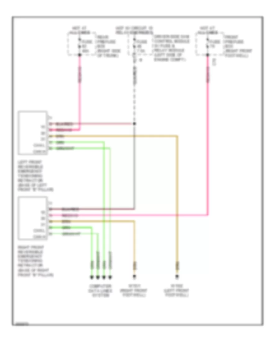
Emergency Seat Belt Tensioners Wiring Diagram for Mercedes-Benz CLS550 2011
List of elements for Emergency Seat Belt Tensioners Wiring Diagram for Mercedes-Benz CLS550 2011:

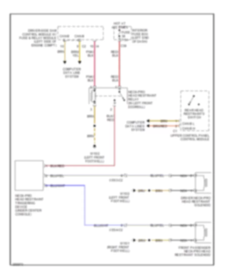
NECK-PRO Head Restraints Wiring Diagram for Mercedes-Benz CLS550 2011
List of elements for NECK-PRO Head Restraints Wiring Diagram for Mercedes-Benz CLS550 2011:
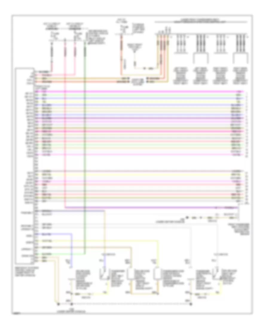
Supplemental Restraint Wiring Diagram (1 of 2) for Mercedes-Benz CLS550 2011
List of elements for Supplemental Restraint Wiring Diagram (1 of 2) for Mercedes-Benz CLS550 2011:
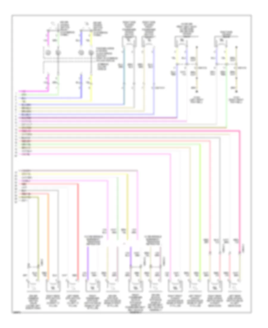
Supplemental Restraint Wiring Diagram (2 of 2) for Mercedes-Benz CLS550 2011
List of elements for Supplemental Restraint Wiring Diagram (2 of 2) for Mercedes-Benz CLS550 2011:
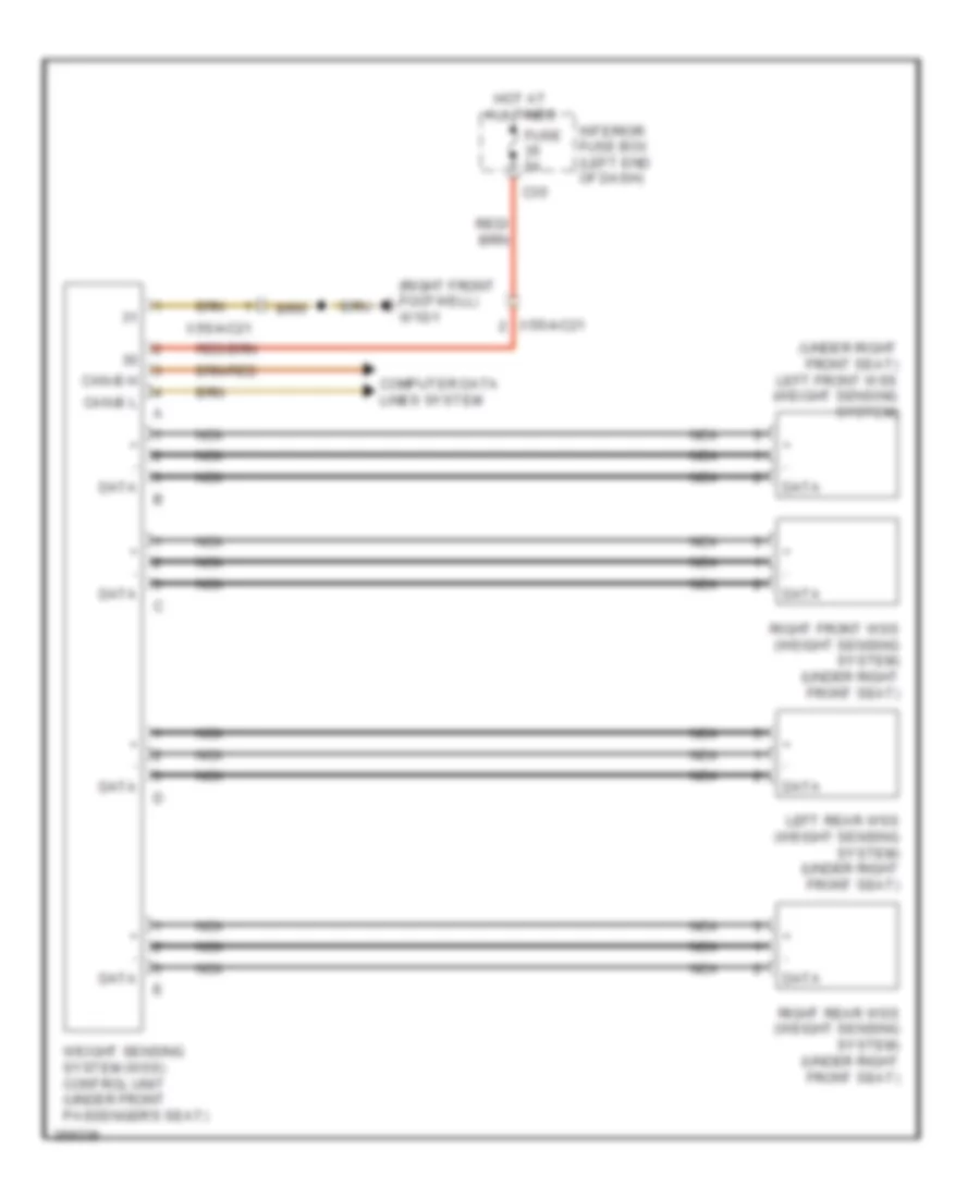
Weight Sensing System Wiring Diagram for Mercedes-Benz CLS550 2011
List of elements for Weight Sensing System Wiring Diagram for Mercedes-Benz CLS550 2011: