ENGINE PERFORMANCE
4.0L
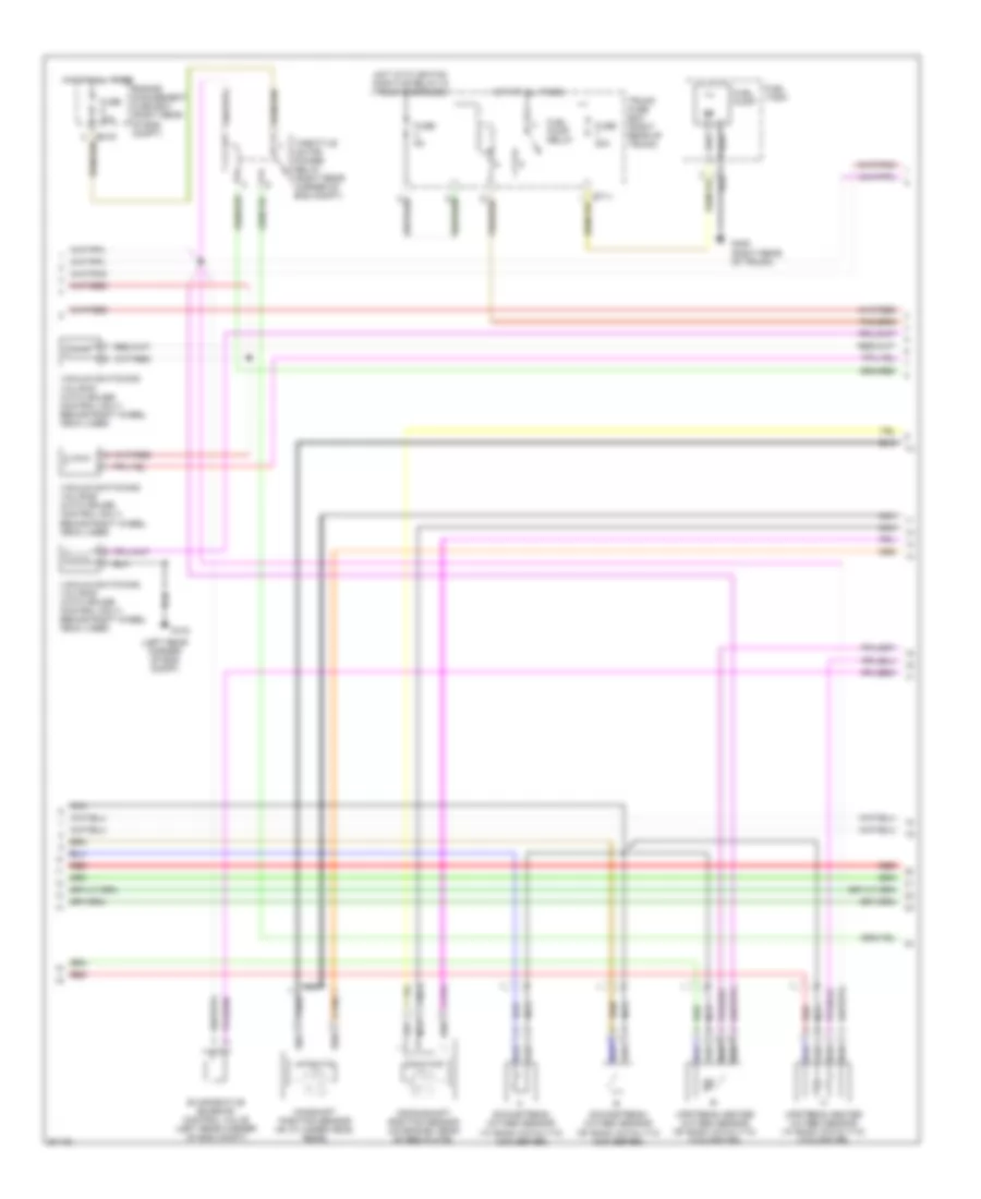
4.0L, Engine Performance Wiring Diagrams (1 of 3) for Jaguar XK8 1997
 https://portal-diagnostov.com/license.html
Automotive Electricians Portal FZCO
Automotive Electricians Portal FZCO
https://portal-diagnostov.com/license.html
https://portal-diagnostov.com/license.html
Automotive Electricians Portal FZCO
Automotive Electricians Portal FZCO
List of elements for 4.0L, Engine Performance Wiring Diagrams (1 of 3) for Jaguar XK8 1997:
- (adjacent to left fascia fuse box) inertia switch
- (left rear corner of eng compt)
- Abs/traction control module (left front of eng compt)
- Acc
- Air conditioning system
- Brake switch (top of brake pedal)
- Cruise control system
- Data link connector (below driver side fuse box)
- Egr valves (rear of throttle assembly)
- Em10 em10 em10
- Em11 em11 em11
- Em13 em13 em13
- Em19
- Em20
- Ems control relay
- Engine compartment fuse box (left front of eng)
- Engine control module (ecm) (left rear of eng compt, near bulkhead connector)
- Engine coolant temperature sensor (rear of eng top hose)
- Engine management fuse box (right rear of eng compt)
- Fuse 10a
- Fuse 5a
- G104
- G105 (right rear corner of eng compt)
- G202 (left side of i/p)
- Gear selector module (front of gear selector assembly)
- Hot at all times
- Ignition positive relay
- Igniton switch
- Lf6
- Lf7
- Major instrument pack
- Mass air flow sensor (rearward of air cleaner)
- Nca
- Off
- P/n
- Park brake switch (below parking brake lever)
- Pedal position & mechanical quard sensors
- Pnk
- Pnk pnk pnk
- Red
- Red red red
- Run
- Start
- Starting/ charging system
- Throttle assembly
- Throttle motor
- Throttle position sensor
- Trans- mission control module (right rear of eng compt)
- Transmission rotary switch (right side of transmission)
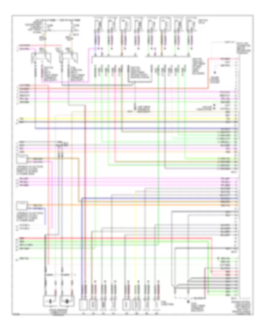
4.0L, Engine Performance Wiring Diagrams (2 of 3) for Jaguar XK8 1997
 https://portal-diagnostov.com/license.html
Automotive Electricians Portal FZCO
Automotive Electricians Portal FZCO
https://portal-diagnostov.com/license.html
https://portal-diagnostov.com/license.html
Automotive Electricians Portal FZCO
Automotive Electricians Portal FZCOList of elements for 4.0L, Engine Performance Wiring Diagrams (2 of 3) for Jaguar XK8 1997:
- (left rear corner of eng compt)
- Bt11
- Camshaft position sensor ("b" cylinder head, rear)
- Crankshaft position sensor (on engine, rear of bed plate)
- Downstream oxygen sensor ("a" bank catalytic converter)
- Downstream oxygen sensor ("b" bank catalytic converter)
- Em19
- Engine management fuse box (right rear of eng compt)
- Evaporative emission control valve (left rear corner of eng compt)
- Fuel pump
- Fuel pump relay
- Fuel tank
- Fuse 20a
- Fuse 30a
- Fuse 5a
- G104
- G405 (right rear of trunk)
- Hot at all times
- Hot with igniton positive relay in trunk energized
- Nca
- Red
- Throttle motor power relay (right rear corner of eng compt)
- Trunk fuse box (right rear of trunk)
- Upstream heated oxygen sensor ("a" bank catalytic converter)
- Upstream heated oxygen sensor ("b" bank catalytic converter)
- Vacuum switching valve #1 (with cruise control only) behind right wheel arch liner)
- Vacuum switching valve #2 (with cruise control only) behind right wheel arch liner)
- Vacuum switching valve #3 (with cruise control only) behind right wheel arch liner)
4.0L, Engine Performance Wiring Diagrams (3 of 3) for Jaguar XK8 1997
 https://portal-diagnostov.com/license.html
Automotive Electricians Portal FZCO
Automotive Electricians Portal FZCO
https://portal-diagnostov.com/license.html
https://portal-diagnostov.com/license.html
Automotive Electricians Portal FZCO
Automotive Electricians Portal FZCOList of elements for 4.0L, Engine Performance Wiring Diagrams (3 of 3) for Jaguar XK8 1997:
- (left rear corner of eng compt)
- Cooling fans system
- Cruise control system
- Data link connector (below driver side fuse box)
- Em13
- Em14
- Em15
- Em19
- Engine compartment fuse box (left front of eng)
- Engine control module (ecm) (left rear of eng compt, near bulkhead connector)
- Fuel injection relay (right rear corner of eng compt)
- Fuel injectors
- Fuse 10a
- G104
- G105 (right rear corner of eng compt)
- Hot at all times
- Ignition coil relay (right rear corner of eng compt)
- Ignition coils
- Ignition module 1 (right rear off eng compt, near bulkhead)
- Ignition module 2 (left rear off eng compt, near bulkhead)
- Knock sensors (under intake manifold)
- Nca
- Red
- Variable valve timing solenoid valve-a (front of "a" bank cylinder head)
- Variable valve timing solenoid valve-b (front of "b" bank cylinder head)

 Čeština
 Dansk
Dansk Deutsch
 Ελληνικά
 English
 English
 Español
 Suomi
Suomi Français
 Français
 עברית
עברית Hrvatski
 Magyar
 Italiano
 한국어
한국어 Nederlands
 Polski
 Português
 Português
 Română
 Русский
 Slovenčina
 Slovenščina
 Svenska
 Türkçe
 中文 (中国)
