ANTI-LOCK BRAKES
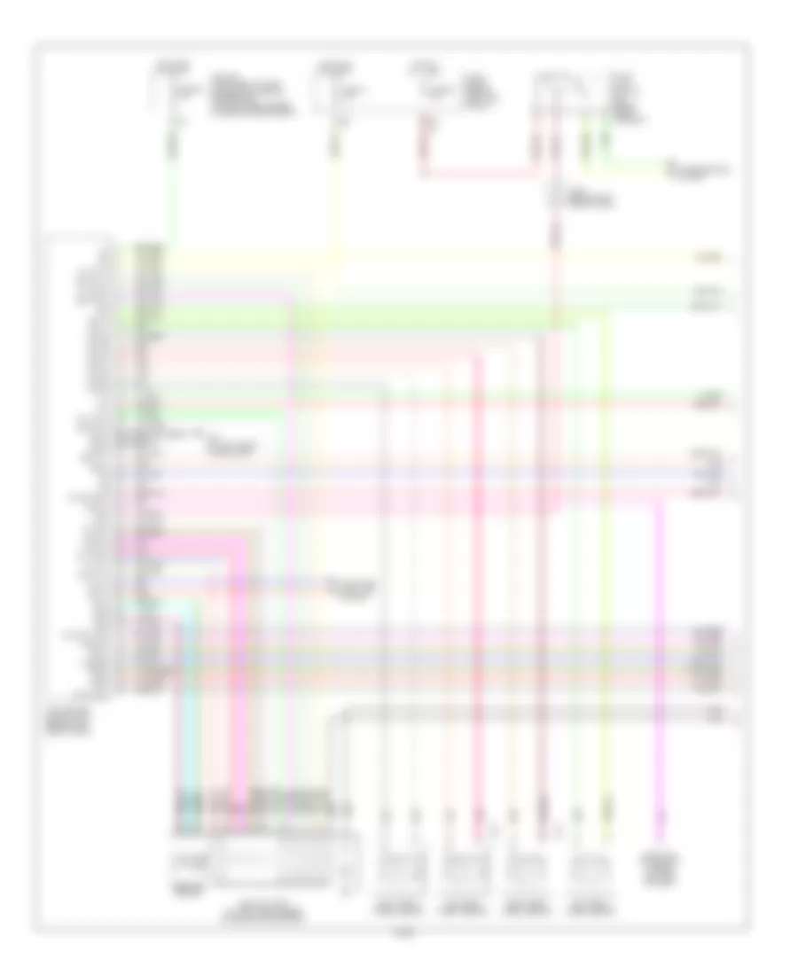
Anti Lock Brake Wiring Diagram, Early Production (1 of 2) for Infiniti G35 2003
 https://portal-diagnostov.com/license.html
Automotive Electricians Portal FZCO
Automotive Electricians Portal FZCO
https://portal-diagnostov.com/license.html
https://portal-diagnostov.com/license.html
Automotive Electricians Portal FZCO
Automotive Electricians Portal FZCO
List of elements for Anti Lock Brake Wiring Diagram, Early Production (1 of 2) for Infiniti G35 2003:
- Abs actuator (at left rear corner of engine compartment)
- Abs w/l
- B113
- Bls
- Can-h
- Can-l
- Computer data line system
- Data link connector (lower left side of dash)
- Diag-k
- Dp fl
- Dp fr
- Dp rl
- Dp rr
- Ds fl
- Ds fr
- Ds rl
- Ds rr
- E101
- E43 (at left front of eng comp)
- Fl mav
- Fl mv-av
- Fl mv-ev
- Fl usv
- Fr mav
- Fr mv-av
- Fr mv-ev
- Fr usv
- Fuse 14 10a
- Fuse 20 10a
- Fuse 88 10a
- Fuse block (behind left kick panel)
- Gnd
- Gnd1
- Gnd2
- Hot at all times
- Hot in on or start
- Ipdm e/r (intelligent power distribution module engine room) (at right rear corner of engine compartment)
- J/c-2 (behind left side of dash)
- Left front wheel sensor
- Left rear wheel sensor
- Lis
- Nca
- Pkb sw
- Pnk
- Pressure sensor
- Psm
- Pss
- Psu
- Red
- Right front wheel sensor
- Right rear wheel sensor
- Rl mv-av
- Rl mv-ev
- Rr mv-av
- Rr mv-ev
- Slip lamp
- Stop light switch (on brake pedal bracket)
- Vcc
- Vdc off lamp
- Vdc off sw
- Vdc/tcs/abs control unit (behind left side of dash)
- Vout
- Yrsm
- Yrsref
- Yrss
- Yrst
- Yrsu
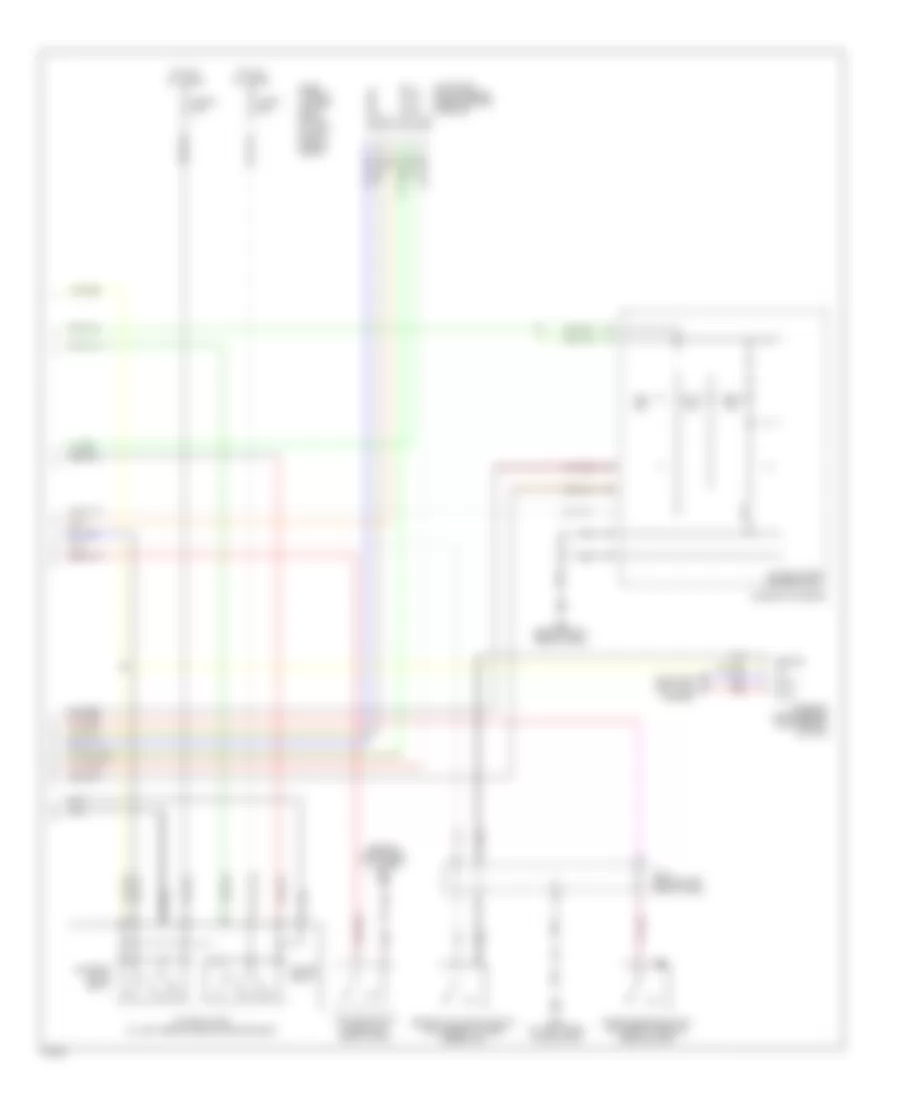
Anti Lock Brake Wiring Diagram, Early Production (2 of 2) for Infiniti G35 2003
 https://portal-diagnostov.com/license.html
Automotive Electricians Portal FZCO
Automotive Electricians Portal FZCO
https://portal-diagnostov.com/license.html
https://portal-diagnostov.com/license.html
Automotive Electricians Portal FZCO
Automotive Electricians Portal FZCOList of elements for Anti Lock Brake Wiring Diagram, Early Production (2 of 2) for Infiniti G35 2003:
- (behind instrument cluster) m30
- 12v
- Abs ind
- Bite
- Brake fluid level switch (on master cylinder reservoir)
- Can-h
- Can-l
- Combination meter
- Computer data line system
- E43 (at left front of eng comp)
- Fuse j 50a
- Fuse k 30a
- Fuse, fusible link box relay block (at left side of engine compt)
- Gnd
- Ground
- Hot at all times
- J/c-1 (behind left side of dash)
- M66 (behind right side of dash)
- Motor relay
- Nca
- Output bs
- Output drs
- Parking brake switch (at base of parking brake lever)
- Red
- Reference
- Slip ind
- Solenoid valve relay
- Steering angle sensor (on steering column)
- Unified meter control unit
- Vdc off
- Vdc off switch (under left side of dash)
- Vdc relay box (at left rear of engine compartment)
- Yaw rate/ side g sensor (under center console)
Anti Lock Brake Wiring Diagram, Late Production (1 of 2) for Infiniti G35 2003
 https://portal-diagnostov.com/license.html
Automotive Electricians Portal FZCO
Automotive Electricians Portal FZCO
https://portal-diagnostov.com/license.html
https://portal-diagnostov.com/license.html
Automotive Electricians Portal FZCO
Automotive Electricians Portal FZCOList of elements for Anti Lock Brake Wiring Diagram, Late Production (1 of 2) for Infiniti G35 2003:
- Abs actuator (at left rear corner of engine compartment)
- Abs w/l
- B113
- Bls
- Can-h
- Can-l
- Computer data line system
- Data link connector (lower left side of dash)
- Diag-k
- Dp fl
- Dp fr
- Dp rl
- Dp rr
- Ds fl
- Ds fr
- Ds rl
- Ds rr
- E101
- E43 (at left front of eng comp)
- Fl mav
- Fl mv-av
- Fl mv-ev
- Fl usv
- Fr mav
- Fr mv-av
- Fr mv-ev
- Fr usv
- Fuse 14 10a
- Fuse 20 10a
- Fuse 88 10a
- Fuse block (behind left kick panel)
- Gnd
- Gnd1
- Gnd2
- Hot at all times
- Hot in on or start
- Ipdm e/r (intelligent power distribution module engine room) (at right rear corner of engine compartment)
- J/c-2 (behind left side of dash)
- Left front wheel sensor
- Left rear wheel sensor
- Lis
- Nca
- Pkb sw
- Pnk
- Pressure sensor
- Psm
- Pss
- Psu
- Red
- Right front wheel sensor
- Right rear wheel sensor
- Rl mv-av
- Rl mv-ev
- Rr mv-av
- Rr mv-ev
- Slip lamp
- Stop light switch (on brake pedal bracket)
- Transmissions system
- Vcc
- Vdc off lamp
- Vdc off sw
- Vdc/tcs/abs control unit (behind left side of dash)
- Vout
- Yrsm
- Yrsref
- Yrss
- Yrst
- Yrsu
Anti Lock Brake Wiring Diagram, Late Production (2 of 2) for Infiniti G35 2003
 https://portal-diagnostov.com/license.html
Automotive Electricians Portal FZCO
Automotive Electricians Portal FZCO
https://portal-diagnostov.com/license.html
https://portal-diagnostov.com/license.html
Automotive Electricians Portal FZCO
Automotive Electricians Portal FZCOList of elements for Anti Lock Brake Wiring Diagram, Late Production (2 of 2) for Infiniti G35 2003:
- (behind instrument cluster) m30
- 12v
- Abs ind
- Bite
- Brake fluid level switch (on master cylinder reservoir)
- Can-h
- Can-l
- Combination meter
- Computer data line system
- E43 (at left front of eng comp)
- Fuse j 50a
- Fuse k 30a
- Fuse, fusible link box relay block (at left side of engine compt)
- Gnd
- Ground
- Hot at all times
- J/c-1 (behind left side of dash)
- M66 (behind right side of dash)
- Motor relay
- Nca
- Output bs
- Output drs
- Parking brake switch (at base of parking brake lever)
- Red
- Reference
- Slip ind
- Solenoid valve relay
- Steering angle sensor (on steering column)
- Unified meter control unit
- Vdc off
- Vdc off switch (under left side of dash)
- Vdc relay box (at left rear of engine compartment)
- Yaw rate/ side g sensor (under center console)

 Čeština
 Dansk
Dansk Deutsch
 Ελληνικά
 English
 English
 Español
 Suomi
Suomi Français
 Français
 עברית
עברית Hrvatski
 Magyar
 Italiano
 한국어
한국어 Nederlands
 Polski
 Português
 Português
 Română
 Русский
 Slovenčina
 Slovenščina
 Svenska
 Türkçe
 中文 (中国)
