ENGINE PERFORMANCE
1.5L HYBRID
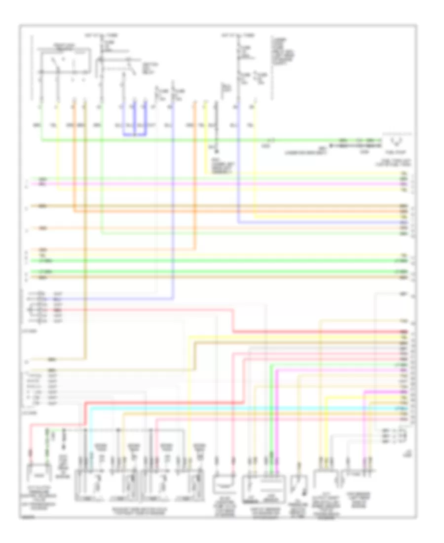
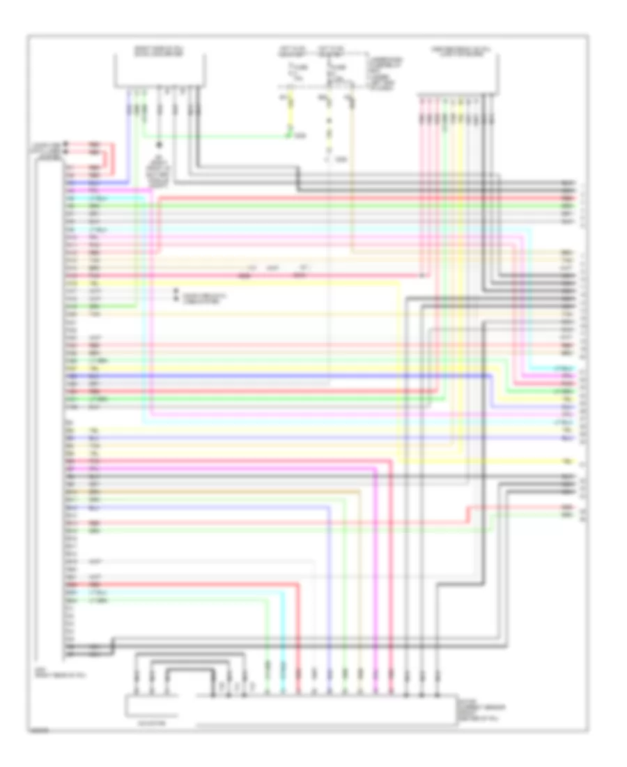
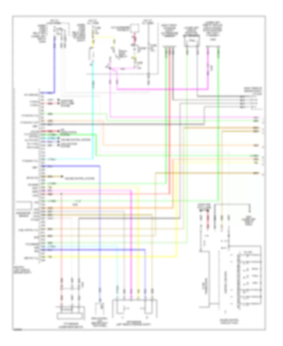
1.5L Hybrid, Engine Controls Wiring Diagram (1 of 5) for Honda Civic Natural Gas 2012
 https://portal-diagnostov.com/license.html
Automotive Electricians Portal FZCO
Automotive Electricians Portal FZCO
https://portal-diagnostov.com/license.html
https://portal-diagnostov.com/license.html
Automotive Electricians Portal FZCO
Automotive Electricians Portal FZCO
List of elements for 1.5L Hybrid, Engine Controls Wiring Diagram (1 of 5) for Honda Civic Natural Gas 2012:
- (lower left side of radiator) ect sensor 2
- (right front corner of engine compt) a/c pressure sensor
- (under rear of vehicle) evap canister vent shut valve
- A10
- A11
- A12
- A13
- A14
- A15
- A16
- A17
- A18
- A19
- A20
- A21
- A22
- A23
- A24
- A25
- A26
- A27
- A28
- A29
- A30
- A31
- A32
- A33
- A34
- A35
- A36
- A37
- A38
- A39
- A40
- A41
- A42
- A43
- A44
- A45
- A46
- A47
- A48
- A49
- Air conditioning system
- App sensor (left rear of engine compt)
- App sensor 1
- App sensor 2
- C222
- Computer data lines system
- Cooling fans system
- Eps control unit (right kick panel)
- F-can transceiver
- Fail-safe circuit
- Forced turning-off circuit
- Forced turning-on circuit
- Ftp sensor (top of fuel tank)
- Fuse 15a
- G503 (left side of dash)
- Gauge control module (tach)
- Hot at all times
- Indicator drive circuit
- J/c c409
- Main circuit
- Mil ind
- Navigation & sound system
- Nep
- Pcm (left side of engine compt)
- Pgm-fi sub- relay
- Pnk
- Red
- Shift interlock system
- Starting/ charging system
- Under- hood fuse/ relay box (left rear of engine compt)
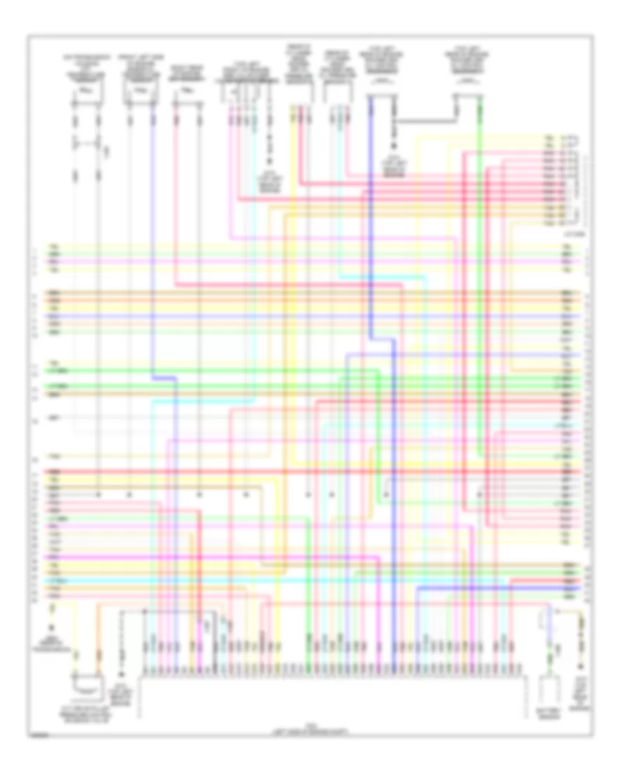
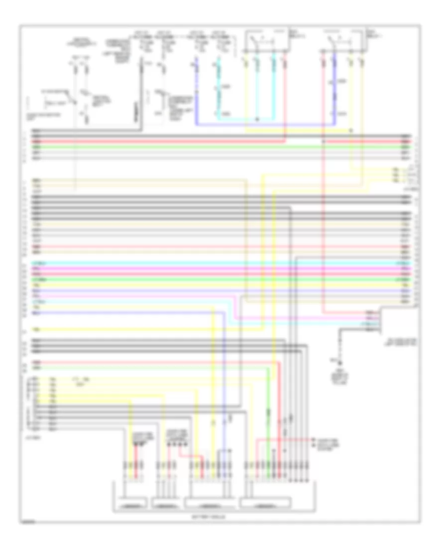
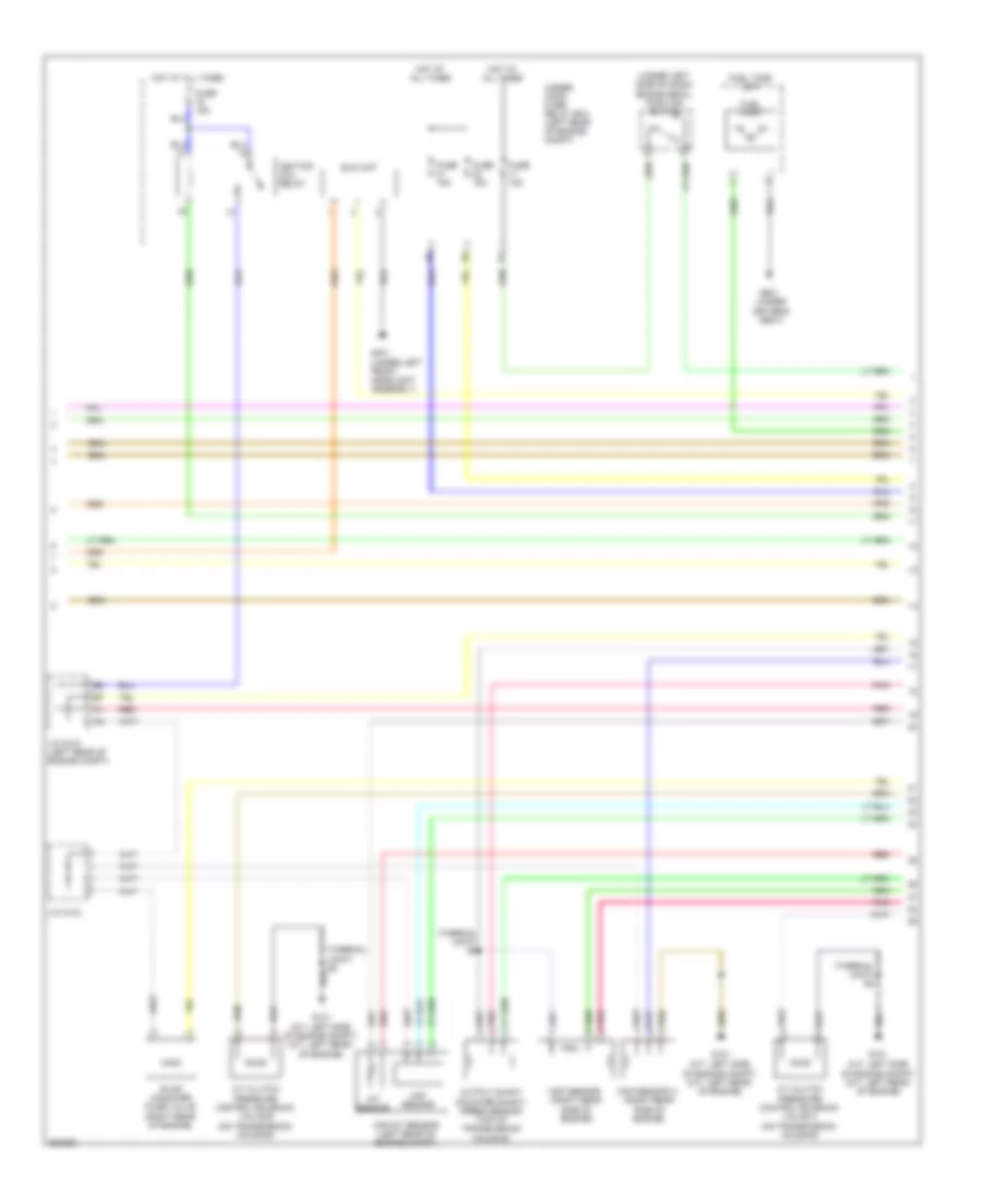
1.5L Hybrid, Engine Controls Wiring Diagram (2 of 5) for Honda Civic Natural Gas 2012
 https://portal-diagnostov.com/license.html
Automotive Electricians Portal FZCO
Automotive Electricians Portal FZCO
https://portal-diagnostov.com/license.html
https://portal-diagnostov.com/license.html
Automotive Electricians Portal FZCO
Automotive Electricians Portal FZCOList of elements for 1.5L Hybrid, Engine Controls Wiring Diagram (2 of 5) for Honda Civic Natural Gas 2012:
- C222
- C229
- C401
- Cvt clutch pressure control solenoid valve (on transmission housing)
- Cvt output shaft (drive pulley) speed sensor (top of transmission housing)
- Eld unit
- Evap canister puge valve (top rear of engine)
- Exhaust side ignition coils (top right side of engine)
- Fuel pump
- Fuel tank unit (top of fuel tank)
- Fuse 1-6 100a
- Fuse 15a
- Fuse 20a
- G101 (top left rear of engine)
- G301 (under left headlight assembly)
- G601 (under driver's seat)
- Hot at all times
- Iat sensor
- Icm
- Ignition coil relay
- J/c c402
- J/c c405
- J/c c406
- Maf sensor
- Maf/iat sensor (on engine air intake duct)
- Map sensor (left rear side of engine)
- Oil pressure switch (near oil filter)
- Pgm-fi main relay 2
- Pnk
- Red
- Spark plug
- Tan
- Under- hood fuse/ relay box (left rear of engine compt)
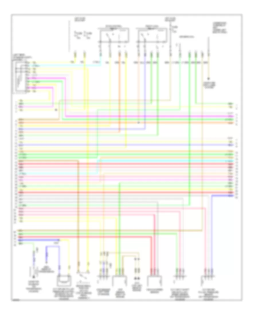
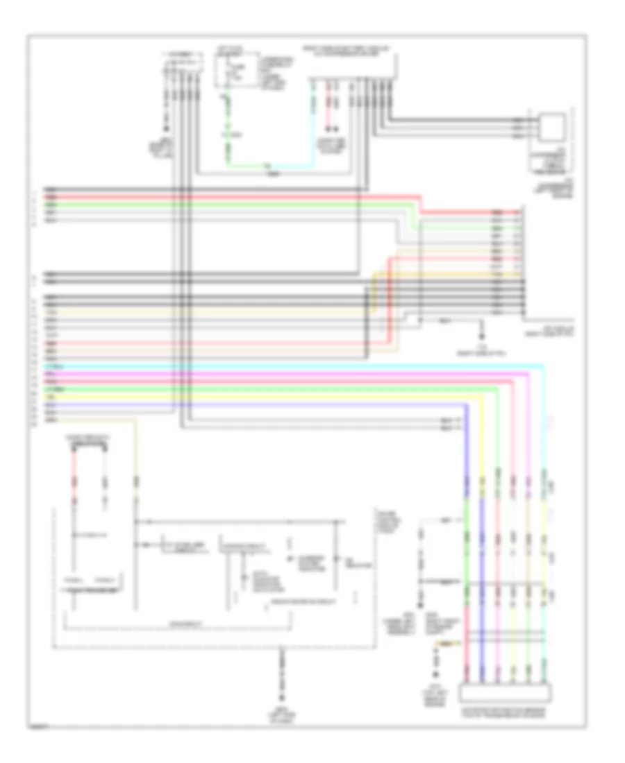
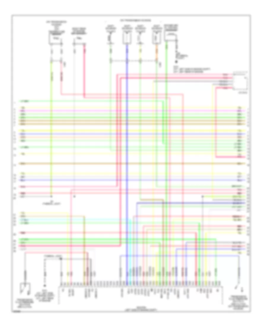
1.5L Hybrid, Engine Controls Wiring Diagram (3 of 5) for Honda Civic Natural Gas 2012
 https://portal-diagnostov.com/license.html
Automotive Electricians Portal FZCO
Automotive Electricians Portal FZCO
https://portal-diagnostov.com/license.html
https://portal-diagnostov.com/license.html
Automotive Electricians Portal FZCO
Automotive Electricians Portal FZCOList of elements for 1.5L Hybrid, Engine Controls Wiring Diagram (3 of 5) for Honda Civic Natural Gas 2012:
- (front left side of engine) engine oil temperature sensor
- (on transmission housing) atf temperature sensor
- (rear of cylinder head) rocker arm oil pressure sensor a
- (rear of cylinder head) rocker arm oil pressure sensor b
- (right rear of engine) ect sensor 1
- (top left front of engine) egr valve & egr valve position sensor
- (top left rear of engine)
- (top left rear of engine) rocker arm oil control solenoid a
- (top left rear of engine) rocker arm oil control solenoid b
- B10
- B11
- B12
- B13
- B14
- B15
- B16
- B17
- B18
- B19
- B20
- B21
- B22
- B23
- B24
- B25
- B26
- B27
- B28
- B29
- B30
- B31
- B32
- B33
- B34
- B35
- B36
- B37
- B38
- B39
- B40
- B41
- B42
- B43
- B44
- B45
- B46
- B47
- B48
- B49
- Battery sensor
- C401
- C405
- Cvt drive pulley pressure control solenoid valve
- G101
- G101 (top left rear of engine)
- G902 (rear of transmission)
- J/c c406
- Pcm (left side of engine compt)
- Pnk
- Red
- Tan
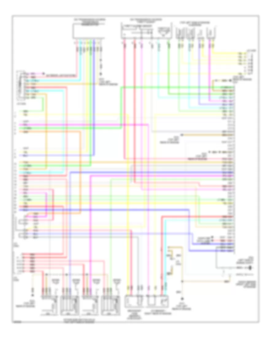
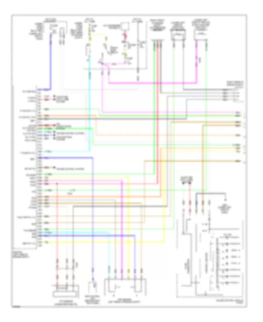
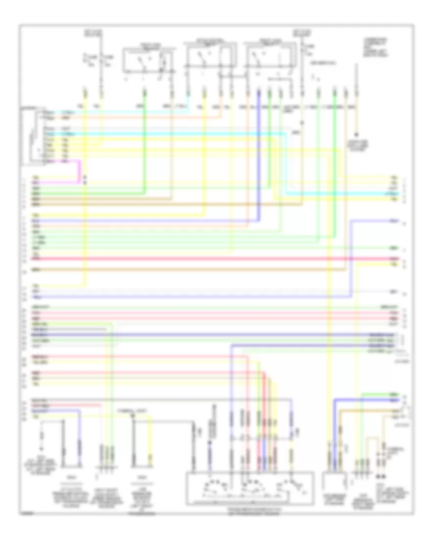
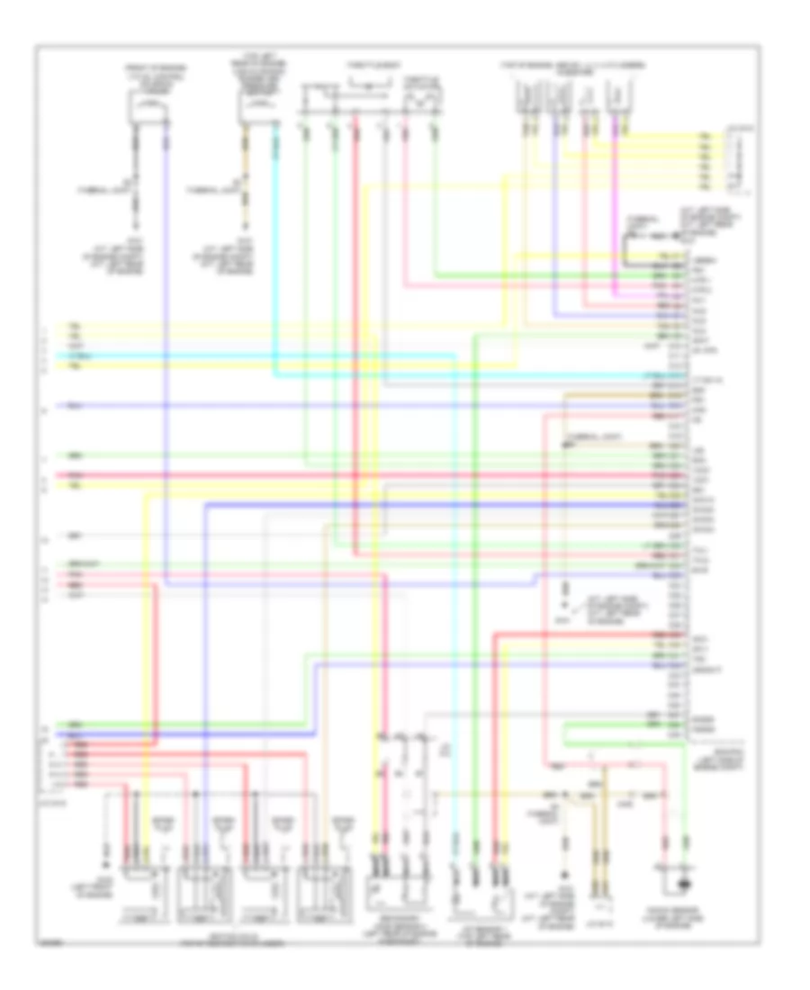
1.5L Hybrid, Engine Controls Wiring Diagram (4 of 5) for Honda Civic Natural Gas 2012
 https://portal-diagnostov.com/license.html
Automotive Electricians Portal FZCO
Automotive Electricians Portal FZCO
https://portal-diagnostov.com/license.html
https://portal-diagnostov.com/license.html
Automotive Electricians Portal FZCO
Automotive Electricians Portal FZCOList of elements for 1.5L Hybrid, Engine Controls Wiring Diagram (4 of 5) for Honda Civic Natural Gas 2012:
- (left rear of engine compt) j/c c402
- Brake pedal position switch (top of brake pedal assembly)
- C13
- C16
- C20
- C24
- C25
- C34
- C401
- C403
- Ckp sensor (left side of engine)
- Cmp sensor (right of engine)
- Computer data lines system
- Cvt driven pulley pressure control solenoid valve (on transmission housing)
- Cvt driven pulley pressure sensor (on transmission housing)
- Cvt input shaft (drive pulley) speed sensor (on transmission housing)
- D10
- D12
- D19
- D23
- Driver's micu
- Etcs control relay
- Fuse 15a
- Fuse 7.5a
- G101 (top left rear of engine)
- G902 (rear of transmission)
- Hot in on or start
- Inhibitor solenoid (on transmission housing)
- Pgm-f1 main relay 1
- Pnk
- Red
- Tan
- Under-dash fuse/relay box (under left end of dash)
- Vehicle speed sensor
1.5L Hybrid, Engine Controls Wiring Diagram (5 of 5) for Honda Civic Natural Gas 2012
 https://portal-diagnostov.com/license.html
Automotive Electricians Portal FZCO
Automotive Electricians Portal FZCO
https://portal-diagnostov.com/license.html
https://portal-diagnostov.com/license.html
Automotive Electricians Portal FZCO
Automotive Electricians Portal FZCOList of elements for 1.5L Hybrid, Engine Controls Wiring Diagram (5 of 5) for Honda Civic Natural Gas 2012:
- (on transmission housing) throttle body
- (on transmission housing) transmission range switch
- (top left rear of engine)
- (top left rear of engine) g101
- (top left side of engine) injectors
- A/f sensor 1 (right rear of engine)
- C10
- C11
- C12
- C13
- C14
- C15
- C16
- C17
- C18
- C19
- C20
- C21
- C22
- C23
- C24
- C25
- C26
- C27
- C28
- C29
- C30
- C31
- C32
- C33
- C34
- C35
- C36
- C37
- C38
- C39
- C40
- C41
- C42
- C43
- C44
- C45
- C46
- C47
- C48
- C49
- Computer data lines system
- Exterior lights system
- G101
- G101 (top left rear of engine)
- Icm
- Intake side ignition coils (top left side of engine)
- J/c c402
- J/c c405
- J/c c406
- Knock sensor (front left side of engine)
- Pcm (left side of engine compt)
- Pnk
- Red
- Secondary ho2s sensor 2 (in exhaust)
- Spark plug
- Tan
- Throttle actuator
- Throttle open sensor
1.5L Hybrid, IMA Wiring Diagram (1 of 3) for Honda Civic Natural Gas 2012
 https://portal-diagnostov.com/license.html
Automotive Electricians Portal FZCO
Automotive Electricians Portal FZCO
https://portal-diagnostov.com/license.html
https://portal-diagnostov.com/license.html
Automotive Electricians Portal FZCO
Automotive Electricians Portal FZCOList of elements for 1.5L Hybrid, IMA Wiring Diagram (1 of 3) for Honda Civic Natural Gas 2012:
- (center front of ipu) junction board
- (right side of ipu) dc-dc converter
- A10
- A11
- A12
- A13
- A14
- A15
- A16
- A17
- A18
- A19
- A20
- A21
- A22
- A23
- A24
- A25
- A26
- A27
- A28
- A29
- A30
- A31
- A32
- B10
- B11
- B12
- B13
- B14
- B15
- B16
- B17
- B18
- B19
- B20
- B21
- B22
- B23
- B24
- C218
- C228
- Computer data lines system
- Fuse 10a
- Fuse 7.5a
- G5 (right front of battery module compt)
- Hot in on or start
- Ima motor
- Mcm (right rear of ipu)
- Motor current sensor (front center of ipu)
- Nca
- Pnk
- Red
- T10
- T11
- T12
- Tan
- Under-dash fuse/relay box (under left end of dash)
1.5L Hybrid, IMA Wiring Diagram (2 of 3) for Honda Civic Natural Gas 2012
 https://portal-diagnostov.com/license.html
Automotive Electricians Portal FZCO
Automotive Electricians Portal FZCO
https://portal-diagnostov.com/license.html
https://portal-diagnostov.com/license.html
Automotive Electricians Portal FZCO
Automotive Electricians Portal FZCOList of elements for 1.5L Hybrid, IMA Wiring Diagram (2 of 3) for Honda Civic Natural Gas 2012:
- Audio navigation unit
- Battery module
- C219
- C222
- C228
- C601
- Central junction box 1
- Central junction box 2
- Computer data lines system
- D28
- Fuse 1-6 100a
- Fuse 10a
- Fuse 7.5a
- G901 (base of right "c" pillar)
- Hot at all times
- Ipu module fan (left side of ipu)
- J/c c602
- J/c c604
- Mcm relay 1
- Mcm relay 2
- Nca
- Pnk
- Q16
- Red
- T101
- Tan
- Under-dash fuse/relay box (under left end of dash)
- Under-hood fuse/relay box (left rear of engine compt)
- V-sensor 1
- V-sensor 2
- V-sensor 3
- V-sensor 4
- W/ navigation
1.5L Hybrid, IMA Wiring Diagram (3 of 3) for Honda Civic Natural Gas 2012
 https://portal-diagnostov.com/license.html
Automotive Electricians Portal FZCO
Automotive Electricians Portal FZCO
https://portal-diagnostov.com/license.html
https://portal-diagnostov.com/license.html
Automotive Electricians Portal FZCO
Automotive Electricians Portal FZCOList of elements for 1.5L Hybrid, IMA Wiring Diagram (3 of 3) for Honda Civic Natural Gas 2012:
- (right front of engine compt)
- (right side of battery module) a/c compressor driver
- (top left rear of engine)
- (under left headlight assembly)
- 10v stabilizer circuit
- A/c compressor (left front of engine)
- A/c compressor clutch/ thermal protector
- Auto idle stop indicator (auto stop)
- C204
- C220
- C227
- C228
- C407
- Charging system indicator
- Computer data lines system
- Dimming circuit
- F can tranceiver
- F-can h
- F-can l
- Fuse 7.5a
- G101
- G301
- G302
- G503 (left side of dash)
- G901 (base of right "c" pillar)
- Gauge control module (tach)
- Hot in on or start
- Ima indicator
- Indicator drive circuit
- J/c c602
- Main circuit
- Motor rotor position sensor (top of transmission housing)
- Mpi module (right side of ipu)
- Nca
- Pnk
- Red
- T16 (right side of ipu)
- Tan
- Under-dash fuse/relay box (under left end of dash)
1.8L
1.8L, Engine Performance Wiring Diagram (1 of 5) for Honda Civic Natural Gas 2012
 https://portal-diagnostov.com/license.html
Automotive Electricians Portal FZCO
Automotive Electricians Portal FZCO
https://portal-diagnostov.com/license.html
https://portal-diagnostov.com/license.html
Automotive Electricians Portal FZCO
Automotive Electricians Portal FZCOList of elements for 1.8L, Engine Performance Wiring Diagram (1 of 5) for Honda Civic Natural Gas 2012:
- (lower left side of radiator) ect sensor 2
- (right front of engine compt) a/c pressure sensor
- (right rear of engine compt)
- (under left end of dash)
- (under left side of vehicle) evap canister vent shut valve
- (under rear seats)
- A/c condenser fan relay
- A/t gear position indicator driving circuit
- A1 ig1 miss sol
- A10
- A11
- A12 a/c mg clutch rly a13
- A14
- A15
- A16
- A17
- A18
- A19
- A20
- A21
- A22
- A23
- A24
- A25
- A26
- A27
- A28
- A29
- A3 f can-h
- A30
- A31
- A32 vsv
- A33
- A34 eld
- A35 vcc5
- A36 vcc4
- A37 ptank
- A38
- A39
- A4 f can-l
- A40 fuel pmp rly cl-
- A41
- A42 scs
- A43
- A44 tw2 sensr
- A45 sg5
- A46 sg4
- A47
- A48 dbw rly cl-
- A49
- A7 fi main rly cl-
- A9 fi main rly out
- Air conditioning system
- App sensor (left rear of engine compt)
- Aps1
- Aps2
- Bk sw nc
- C232
- Clutch sw
- Computer data lines system
- Control circuits
- Cooling fans system
- Cruise control system
- D28
- Diode e
- Ecm/pcm (left side of engine compt)
- Eps control unit (behind right kick panel)
- Fan hi sig
- Fi sub rly cl-
- Ftp sensor
- Fuse 10a
- Fuse 15a
- Fuse 15a (a/t)
- Fuse 7.5a
- G503 (under left side of dash)
- Gauge control module (tach)
- Hot at all times
- Hot in on or start
- J/c c417
- Mil ind
- Nep
- Pd snsr
- Pgm-fi sub- relay
- Pnk
- Red
- Rly ctrl
- S232
- Sg6
- Stp sw
- Transceiver f-can
- Under- dash fuse/ relay box
- Under- hood fuse/ relay box (left rear of engine compt)
- Vcc6
1.8L, Engine Performance Wiring Diagram (2 of 5) for Honda Civic Natural Gas 2012
 https://portal-diagnostov.com/license.html
Automotive Electricians Portal FZCO
Automotive Electricians Portal FZCO
https://portal-diagnostov.com/license.html
https://portal-diagnostov.com/license.html
Automotive Electricians Portal FZCO
Automotive Electricians Portal FZCOList of elements for 1.8L, Engine Performance Wiring Diagram (2 of 5) for Honda Civic Natural Gas 2012:
- (a/t: left side of engine compt) (m/t: left rear of engine)
- (in top of fuel tank) fuel tank unit
- (thermal joint) s2
- (thermal joint) s5
- (under
- (under left side of dash) brake pedal position switch
- A/t clutch pressure control solenoid valve a (on transmission housing)
- A/t clutch pressure control solenoid valve b (on transmission housing)
- Driver's seat)
- Eld unit
- Evap canister purge valve (right rear of engine)
- Fuel pump
- Fuse 15a
- G101
- G101 (a/t: left side of engine compt) (m/t: left rear of engine)
- G301 (under left front headlight assembly)
- G601
- Hot at all times
- Iat sensor
- Ignition coil relay
- Imt actuator (right front of engine)
- J/c c404
- Maf sensor
- Maf/iat sensor (left rear of engine compt)
- Map sensor (right rear side of engine)
- Output shaft (counter shaft) speed sensor (top of transmission housing)
- Under- hood fuse/ relay box (left rear of engine compt)
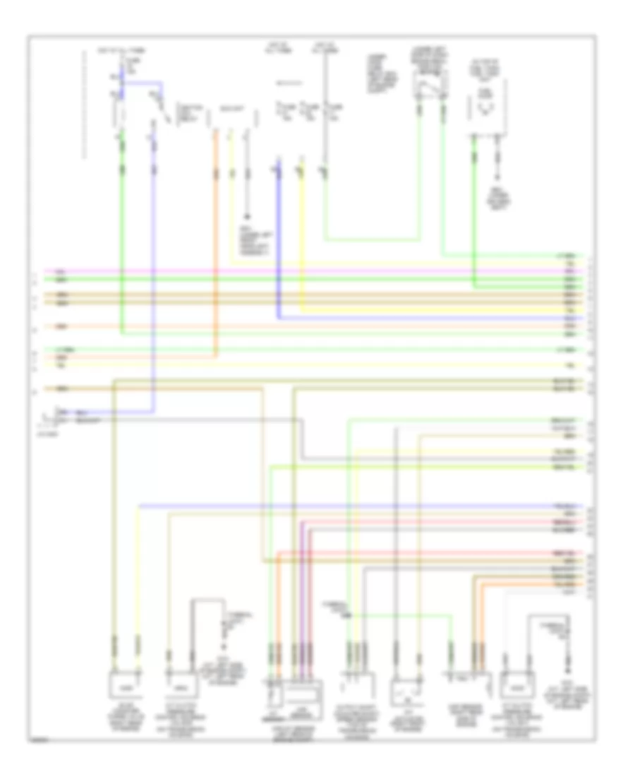
1.8L, Engine Performance Wiring Diagram (3 of 5) for Honda Civic Natural Gas 2012
 https://portal-diagnostov.com/license.html
Automotive Electricians Portal FZCO
Automotive Electricians Portal FZCO
https://portal-diagnostov.com/license.html
https://portal-diagnostov.com/license.html
Automotive Electricians Portal FZCO
Automotive Electricians Portal FZCOList of elements for 1.8L, Engine Performance Wiring Diagram (3 of 5) for Honda Civic Natural Gas 2012:
- (a/t: left side of engine compt) (m/t: left rear of engine)
- (on transmission housing)
- (on transmission housing) atf temperature sensor
- (right rear of engine) ect sensor 1
- (thermal joint) s2
- (top front of engine) rocker arm oil control solenoid
- (top left rear of engine) egr valve & egr valve position sensor
- Atp fwd
- Atp rvs
- Atp2-1
- Atpd
- Atpd3
- Atpn
- Atpp
- Atpr
- B10
- B11
- B12
- B13
- B14
- B15
- B16
- B17
- B18
- B19
- B20
- B21
- B22
- B23
- B24
- B25
- B26
- B27
- B28
- B29
- B30
- B31
- B32
- B33
- B34
- B35
- B36
- B37
- B38
- B39
- B40
- B41
- B42
- B43
- B44
- B45
- B46
- B47
- B48
- B49
- C401
- E egr
- Ecm/pcm (left side of engine compt)
- Ect1
- Egr l
- G101
- J/c c407 (a/t) j/c c405 (m/t)
- Linear a
- Linear b
- Linear c
- Map (pb)
- Op2 sw
- Op3 sw
- Pc sol
- Pla
- Red
- S2 (thermal joint)
- S4 (thermal joint)
- Sg2
- Sh a
- Sh d
- Shift solenoid
- So2
- So2ht
- Svsm
- Svsp
- Tat f
- Transmission fluid pressure switch a (2nd clutch) (on transmission housing)
- Transmission fluid pressure switch b (3rd clutch)
- Valve a
- Valve b
- Valve c
- Valve d
- Vcc2
- Vgm
- Vgp
- Vt sol
1.8L, Engine Performance Wiring Diagram (4 of 5) for Honda Civic Natural Gas 2012
 https://portal-diagnostov.com/license.html
Automotive Electricians Portal FZCO
Automotive Electricians Portal FZCO
https://portal-diagnostov.com/license.html
https://portal-diagnostov.com/license.html
Automotive Electricians Portal FZCO
Automotive Electricians Portal FZCOList of elements for 1.8L, Engine Performance Wiring Diagram (4 of 5) for Honda Civic Natural Gas 2012:
- (not used)
- (thermal joint)
- (thermal joint) s3
- 2-1
- A/t clutch pressure control solenoid valve c (on transmission housing)
- A16
- A17
- A19
- A20
- A21
- A22
- A23
- B15
- B20
- B21
- C13
- C16
- C20
- C25
- C34
- C35
- C406
- Ckp sensor (left side of engine)
- Cmp sensor (right rear of engine)
- Computer data lines system
- D10
- D12
- D19
- Driver's micu
- Etcs control relay
- Fuse 15a
- Fuse 7.5a
- G101 (a/t: left side of engine compt) (m/t: left rear of engine)
- Hot in on or start
- Input shaft (main shaft) speed sensor (a/t) (on transmission housing)
- J/c c404
- Line pressure solenoid valve a (left front of transmission)
- P13
- Pgm-f1 main relay 1
- Pgm-fi main relay 2
- Pnk
- Red
- Starting/ charging system
- Transmission range switch (on transmission housing)
- Under-dash fuse/relay box (under left end of dash)
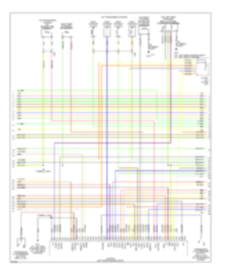
1.8L, Engine Performance Wiring Diagram (5 of 5) for Honda Civic Natural Gas 2012
 https://portal-diagnostov.com/license.html
Automotive Electricians Portal FZCO
Automotive Electricians Portal FZCO
https://portal-diagnostov.com/license.html
https://portal-diagnostov.com/license.html
Automotive Electricians Portal FZCO
Automotive Electricians Portal FZCOList of elements for 1.8L, Engine Performance Wiring Diagram (5 of 5) for Honda Civic Natural Gas 2012:
- (a/t: left side of engine compt) (m/t: left rear of engine)
- (top of engine, above respective cylinders) injectors
- A/f sensor 1 (top left rear of engine)
- Afc1
- Afht
- Afv1
- Barometer sensor
- C10
- C11
- C12
- C13
- C14
- C15
- C16
- C17
- C18
- C19
- C20
- C21
- C22
- C23
- C24
- C25
- C26
- C27
- C28
- C29
- C30
- C31
- C32
- C33
- C34
- C35
- C36
- C37
- C38
- C39
- C40
- C402
- C41
- C42
- C43
- C44
- C45
- C46
- C47
- C48
- C49
- Crank
- Ecm/pcm (left side of engine compt)
- G101
- G101 (a/t: left side of engine compt) (m/t: left rear of engine)
- Icm
- Ig1 (f/p)
- Ig101a
- Ig102a
- Ig103a
- Ig104a
- Ignition coils (top of respective cylinder)
- Inj1
- Inj2
- Inj3
- Inj4
- J/c c407 (a/t) j/c c405 (m/t)
- Joint) (thermal s2
- Knock
- Knock sensor (top of engine)
- Ksgnd
- Lg2
- Mtr 1
- Mtr 2
- Nca
- Pg1
- Red
- Rocker arm oil control switch
- S3 (thermal joint)
- Secondary ho2s sensor 2 (left rear of engine, in exhaust)
- Sg1
- Sg3
- Sh b
- Shc
- So2sg
- Spark plug
- Tdc
- Thl1
- Thl2
- Throttle actuator
- Throttle body
- Vbdbw
- Vcc1
- Vcc3
- Vtm
2.4L
2.4L, Engine Performance Wiring Diagram (1 of 5) for Honda Civic Natural Gas 2012
 https://portal-diagnostov.com/license.html
Automotive Electricians Portal FZCO
Automotive Electricians Portal FZCO
https://portal-diagnostov.com/license.html
https://portal-diagnostov.com/license.html
Automotive Electricians Portal FZCO
Automotive Electricians Portal FZCOList of elements for 2.4L, Engine Performance Wiring Diagram (1 of 5) for Honda Civic Natural Gas 2012:
- (lower left side of radiator) ect sensor 2
- (right front of engine compt) a/c pressure sensor
- (right rear of engine compt)
- (under left end of dash)
- (under left side of vehicle) (usa & canada) evap canister vent shut valve
- (under rear seats)
- A/c condenser fan relay
- A/t gear position indicator driving circuit
- A1 ig1 miss sol
- A10
- A11
- A12 a/c mg clutch rly a13
- A14
- A15
- A16
- A17
- A18
- A19
- A20
- A21
- A22
- A23
- A24
- A25
- A26
- A27
- A28
- A29
- A3 f can-h
- A30
- A31
- A32 vsv
- A33
- A34 eld
- A35 vcc5
- A36 vcc4
- A37 ptank
- A38
- A39
- A4 f can-l
- A40 fuel pmp rly cl-
- A41
- A42 scs
- A43
- A44 tw2 sensr
- A45 sg5
- A46 sg4
- A47
- A48 dbw rly cl-
- A49
- A7 fi main rly cl-
- A9 fi main rly out
- Air conditioning system
- App sensor (left rear of engine compt)
- Aps1
- Aps2
- Barometer sensor
- Bk sw nc
- C222
- C232
- Clutch sw
- Computer data lines system
- Control circuits
- Cooling fans system
- Cruise control system
- D28
- Diode e
- Ecm/pcm (left side of engine compt)
- Eps control unit (behind right kick panel)
- Fan hi sig
- Fi sub rly cl-
- Ftp sensor
- Fuse 10a
- Fuse 15a
- Fuse 7.5a
- G503 (under left side of dash)
- Gauge control module (tach)
- Hot at all times
- J/c c420
- Mil ind
- Nep
- Pd snsr
- Pgm-fi sub- relay
- Pnk
- Red
- Rly ctrl
- Sg6
- Stp sw
- Transceiver f-can
- Under- dash fuse/ relay box
- Under- hood fuse/ relay box (left rear of engine compt)
- Vcc6
2.4L, Engine Performance Wiring Diagram (2 of 5) for Honda Civic Natural Gas 2012
 https://portal-diagnostov.com/license.html
Automotive Electricians Portal FZCO
Automotive Electricians Portal FZCO
https://portal-diagnostov.com/license.html
https://portal-diagnostov.com/license.html
Automotive Electricians Portal FZCO
Automotive Electricians Portal FZCOList of elements for 2.4L, Engine Performance Wiring Diagram (2 of 5) for Honda Civic Natural Gas 2012:
- (a/t: left side of engine compt) (m/t: left rear of engine)
- (thermal joint) s2
- (thermal joint) s5
- (under
- (under left side of dash) brake pedal position switch
- A/t clutch pressure control solenoid valve a (on transmission housing)
- A/t clutch pressure control solenoid valve b (on transmission housing)
- Driver's seat)
- Eld unit
- Evap canister puge valve (right rear of engine)
- Fuel pump
- Fuel tank unit
- Fuse 15a
- G101
- G101 (a/t: left side of engine compt) (m/t: left rear of engine)
- G301 (under left front headlight assembly)
- G601
- Hot at all times
- Iat sensor
- Ignition coil relay
- J/c c410 (left rear of engine compt)
- J/c c412
- Maf sensor
- Maf/iat sensor (left rear of engine compt)
- Map sensor (right rear side of engine)
- Map sensor a (right rear side of engine)
- Output shaft (counter shaft) speed sensor (top of transmission housing)
- Pnk
- Red
- Under- hood fuse/ relay box (left rear of engine compt)
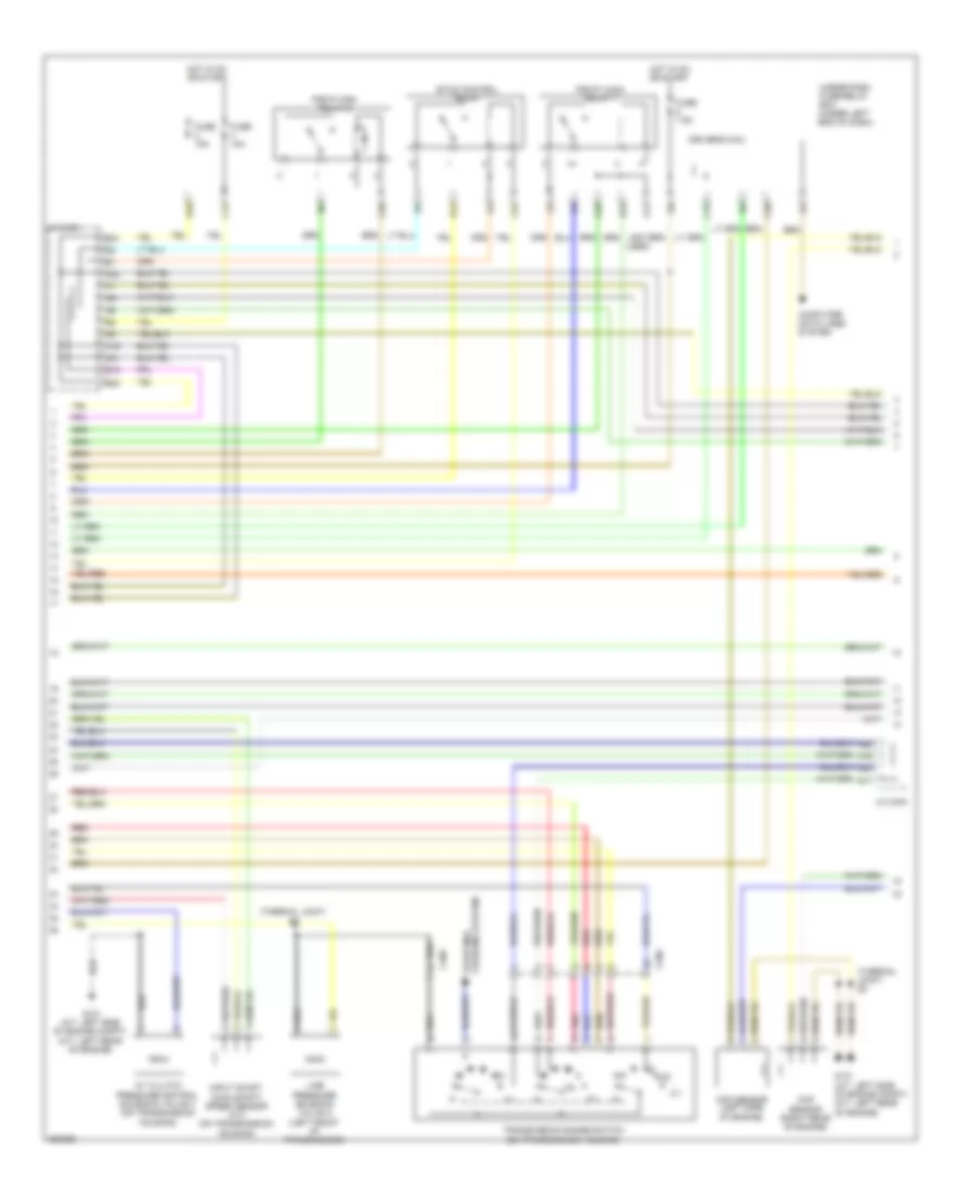
2.4L, Engine Performance Wiring Diagram (3 of 5) for Honda Civic Natural Gas 2012
 https://portal-diagnostov.com/license.html
Automotive Electricians Portal FZCO
Automotive Electricians Portal FZCO
https://portal-diagnostov.com/license.html
https://portal-diagnostov.com/license.html
Automotive Electricians Portal FZCO
Automotive Electricians Portal FZCOList of elements for 2.4L, Engine Performance Wiring Diagram (3 of 5) for Honda Civic Natural Gas 2012:
- (a/t: left side of engine compt) (m/t: left rear of engine)
- (on transmission housing)
- (on transmission housing) (a/t) atf temperature sensor
- (right rear of engine) ect sensor 1
- (thermal joint) s2
- Atp fwd
- Atp rvs
- Atp2-1
- Atpd
- Atpd3
- Atpn
- Atpp
- Atpr
- B10
- B11
- B12
- B13
- B14
- B15
- B16
- B17
- B18
- B19
- B20
- B21
- B22
- B23
- B24
- B25
- B26
- B27
- B28
- B29
- B30
- B31
- B32
- B33
- B34
- B35
- B36
- B37
- B38
- B39
- B40
- B41
- B42
- B43
- B44
- B45
- B46
- B47
- B48
- B49
- C401
- Ecm/pcm (left side of engine compt)
- G101
- G101 (a/t: left side of engine compt) (m/t: left rear of engine)
- J/c c412
- Linear a
- Linear b
- Linear c
- Map (pb)
- Op2 sw
- Op3 sw
- Pc sol
- Pla
- Pnk
- Red
- Rocker arm oil control solenoid
- S4 (thermal joint)
- Sg2
- Sh a
- Sh d
- Shift solenoid
- So2
- So2ht
- Tat f
- Transmission fluid pressure switch a (2nd clutch) (on transmission housing)
- Transmission fluid pressure switch b (3rd clutch)
- Valve a
- Valve b
- Valve c
- Valve d
- Vcc2
- Vgm
- Vgp
- Vt sol in
2.4L, Engine Performance Wiring Diagram (4 of 5) for Honda Civic Natural Gas 2012
 https://portal-diagnostov.com/license.html
Automotive Electricians Portal FZCO
Automotive Electricians Portal FZCO
https://portal-diagnostov.com/license.html
https://portal-diagnostov.com/license.html
Automotive Electricians Portal FZCO
Automotive Electricians Portal FZCOList of elements for 2.4L, Engine Performance Wiring Diagram (4 of 5) for Honda Civic Natural Gas 2012:
- (not used)
- (thermal joint)
- (thermal joint) s3
- 2-1
- A/t clutch pressure control solenoid valve c (on transmission housing)
- A12
- A14
- A15
- A16
- A17
- A18
- A20
- A22
- A23
- B10
- B12
- B22
- C13
- C16
- C20
- C25
- C34
- C35
- C406
- C411
- Ckp sensor (left side of engine)
- Cmp sensor b (right rear of engine)
- Computer data lines system
- D10
- D12
- D19
- Driver's micu
- Etcs control relay
- Fuse 15a
- Fuse 7.5a
- G101 (a/t: left side of engine compt) (m/t: left rear of engine)
- Hot in on or start
- Input shaft (main shaft) speed sensor (on transmission housing)
- J/c c404
- J/c c410
- Line pressure solenoid valve a (left front of transmission)
- P13
- Pgm-f1 main relay 1
- Pgm-fi main relay 2
- Pnk
- Red
- Starting/ charging system
- Transmission range switch (on transmission housing)
- Under-dash fuse/relay box (under left end of dash)
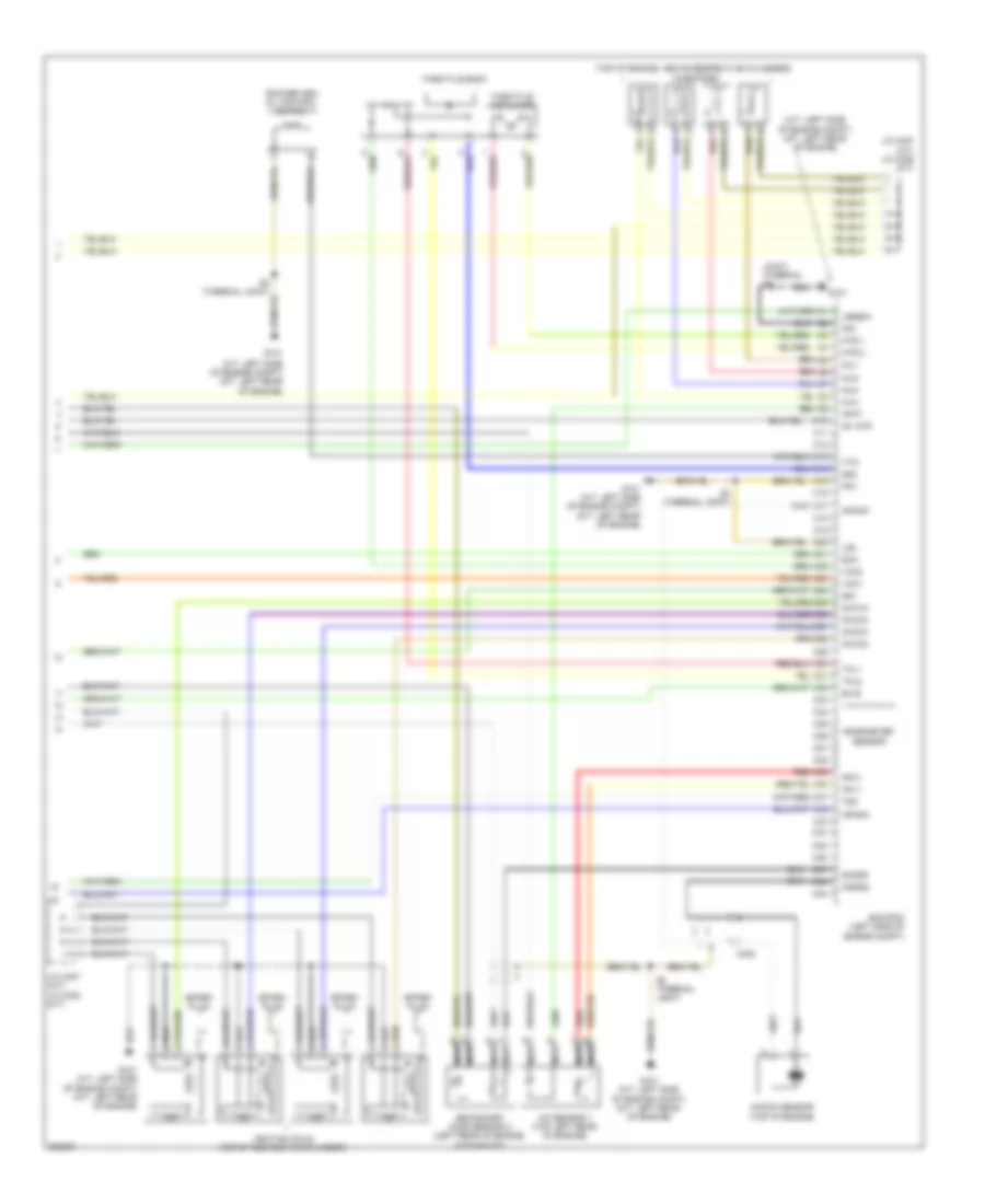
2.4L, Engine Performance Wiring Diagram (5 of 5) for Honda Civic Natural Gas 2012
 https://portal-diagnostov.com/license.html
Automotive Electricians Portal FZCO
Automotive Electricians Portal FZCO
https://portal-diagnostov.com/license.html
https://portal-diagnostov.com/license.html
Automotive Electricians Portal FZCO
Automotive Electricians Portal FZCOList of elements for 2.4L, Engine Performance Wiring Diagram (5 of 5) for Honda Civic Natural Gas 2012:
- (a/t: left side of engine compt) (m/t: left rear of engine)
- (front of engine)
- (thermal joint) s2
- (thermal joint) s3
- (top left rear of engine) (usa & canada) rocker arm pressure switch
- (top of engine, above 1, 2, 3, 4 cylinders) injectors
- A/f sensor 1 (top left rear of engine)
- A20
- A21
- Afc1
- Afht
- Afv1
- C10
- C11
- C12
- C13
- C14
- C15
- C16
- C17
- C18
- C19
- C20
- C21
- C22
- C23
- C24
- C25
- C26
- C27
- C28
- C29
- C30
- C31
- C32
- C33
- C34
- C35
- C36
- C37
- C38
- C39
- C40
- C408
- C41
- C42
- C43
- C44
- C45
- C46
- C47
- C48
- C49
- Cam
- Crank p
- Ecm/pcm (left side of engine compt)
- G101
- G101 (a/t: left side of engine compt) (m/t: left rear of engine)
- G102 (left front of engine)
- Icm
- Ig1 (f/p)
- Ig101a
- Ig102a
- Ig103a
- Ig104a
- Ignition coils (top of respective cylinder)
- Inj1
- Inj2
- Inj3
- Inj4
- J/c
- J/c c410
- J/c c412
- Knock sensor (lower left side of engine)
- Ksgnd
- Lg2
- Mtr 1
- Mtr 2
- Nca
- Pg1
- Pnk
- Red
- S2 (thermal joint)
- S3 (thermal joint)
- Secondary ho2s sensor 2 (left rear of engine in exhaust)
- Sg1
- Sg3
- Sh b
- Shc
- So2sg
- Spark plug
- Tan
- Tdc
- Thl1
- Thl2
- Throttle actuator
- Throttle body
- Vbdbw
- Vcc1
- Vcc3
- Vt sw in
- Vtc oil control solenoid valve

 Čeština
 Dansk
Dansk Deutsch
 Ελληνικά
 English
 English
 Español
 Suomi
Suomi Français
 Français
 עברית
עברית Hrvatski
 Magyar
 Italiano
 한국어
한국어 Nederlands
 Polski
 Português
 Português
 Română
 Русский
 Slovenčina
 Slovenščina
 Svenska
 Türkçe
 中文 (中国)
