POWER DISTRIBUTION
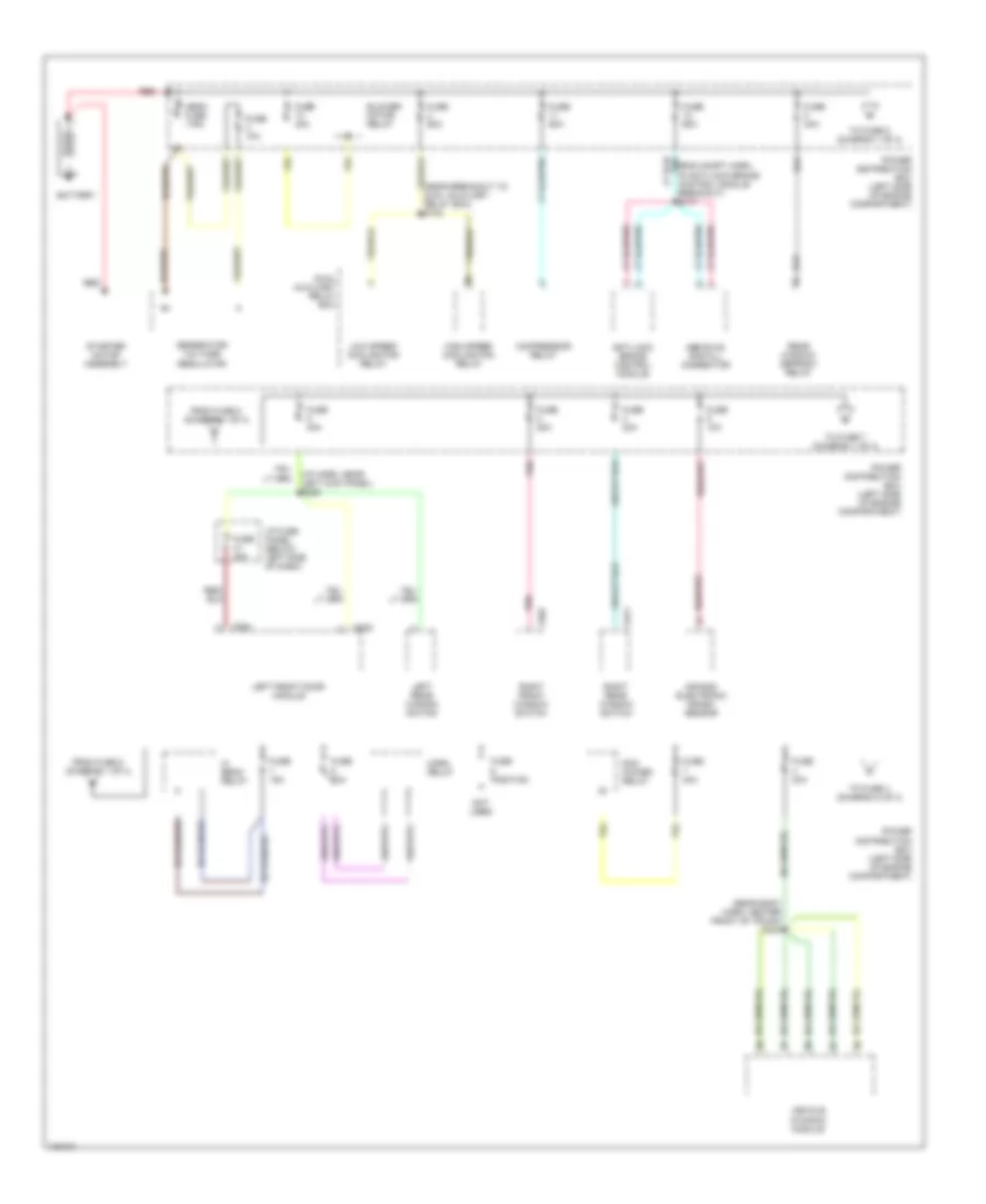
Power Distribution Wiring Diagram (1 of 4) for Lincoln Continental 1998
 https://portal-diagnostov.com/license.html
Automotive Electricians Portal FZCO
Automotive Electricians Portal FZCO
https://portal-diagnostov.com/license.html
https://portal-diagnostov.com/license.html
Automotive Electricians Portal FZCO
Automotive Electricians Portal FZCO
List of elements for Power Distribution Wiring Diagram (1 of 4) for Lincoln Continental 1998:
- (eng compt harn, in anti-lock brake control module breakout) s117
- (i/p harn, near left kick panel) s226
- (near breakout to dual auxiliary relay box) s142
- (rear body harn, center front of trunk) s434
- Abs evac and fill connector
- Air bag electronic crash sensor
- Anti-lock brake control module
- Battery
- Blower motor relay
- C522
- C524
- C601
- C811
- Compressor relay
- Dual auxiliary relay box
- From fuse 5 (diagram 1 of 4)
- From fuse 8 (diagram 1 of 4)
- Fuse 10a
- Fuse 15a
- Fuse 20a
- Fuse 30a
- Fuse 40a
- Fuse 60a
- Fuse position
- Generator/ voltage regulator
- Hi beam relay
- High speed cooling fan relay
- Horn relay
- I/p fuse panel (below left side of dash)
- Left front door module
- Left rear window switch
- Low speed cooling fan relay
- Mega fuse 175a
- Not used
- Pcm power relay
- Pnk
- Power distribution box (left side of engine compartment)
- Rear window defrost relay
- Red
- Right front window switch
- Right rear window switch
- Starter motor assembly
- To fuse 4 (diagram 2 of 4)
- To fuse 5 (diagram 1 of 4)
- To fuse 7 (diagram 1 of 4)
- Vehicle dynamic module
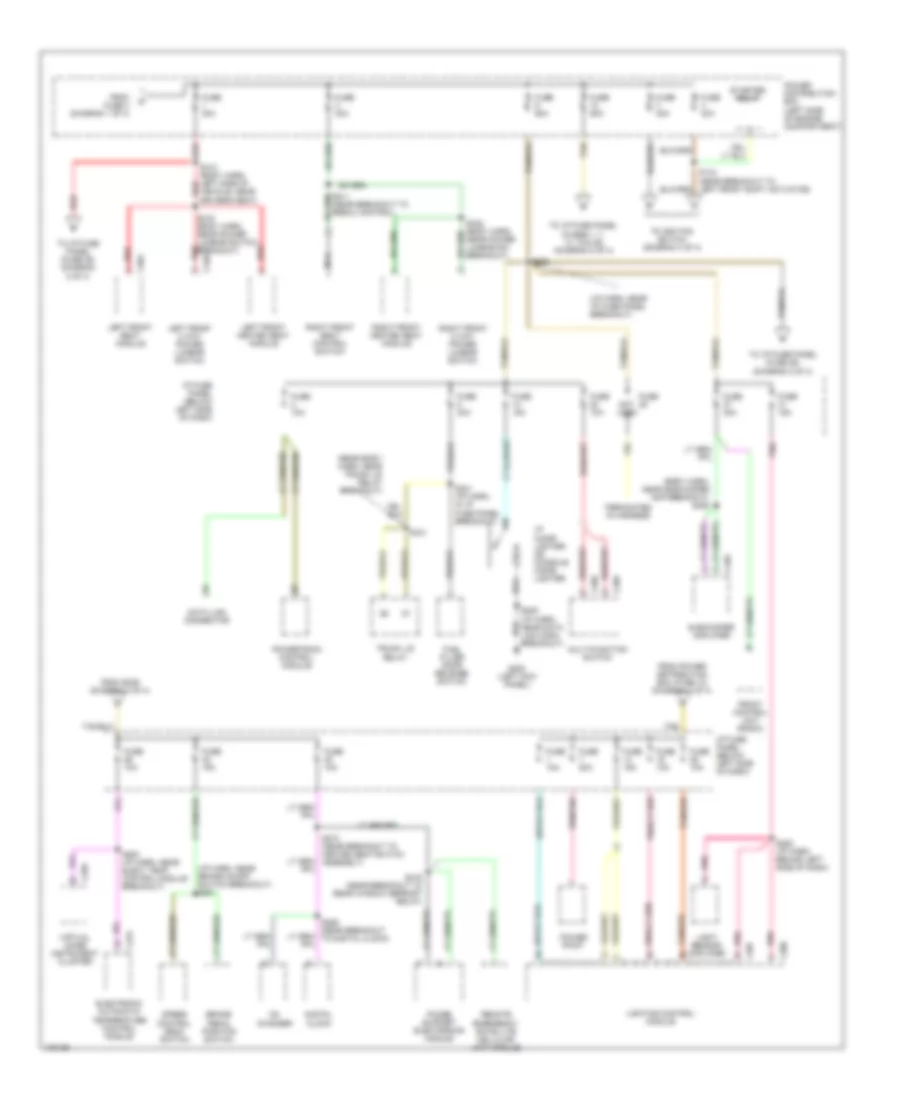
Power Distribution Wiring Diagram (2 of 4) for Lincoln Continental 1998
 https://portal-diagnostov.com/license.html
Automotive Electricians Portal FZCO
Automotive Electricians Portal FZCO
https://portal-diagnostov.com/license.html
https://portal-diagnostov.com/license.html
Automotive Electricians Portal FZCO
Automotive Electricians Portal FZCOList of elements for Power Distribution Wiring Diagram (2 of 4) for Lincoln Continental 1998:
- (body harn, near subwoofer amp breakout) s406
- (i/p harn, near brake on/off switch breakout) s251
- (i/p harn, near i/p fuse panel breakout)
- (rear body harn, near trunk lid relay breakout)
- Brake pedal position switch
- Breakout)
- C207
- C208
- C256
- C268
- C269
- C275
- C348
- C362
- C456
- Cd changer
- Data link connector
- Digital clock
- Electronic automatic temperature control module
- From fuse 4 (diagram 1 of 4)
- From power distribution box (fuse 10) (diagram 2 of 4)
- From s239 (diagram 2 of 4)
- Front control unit (radio)
- Fuel filler door release switch
- Fuse
- Fuse 10a
- Fuse 15a
- Fuse 20a
- Fuse 30a
- Fuse 40a
- Fuse 60a
- G200 (left kick panel)
- I/p cigar lighter or console cigar lighter
- I/p fuse panel (below left side of dash)
- Left front 2 way power lumbar switch
- Left front heated seat module
- Left front seat module
- Light sensor/ amplifier
- Lighting control module
- Multi-function switch
- Nca
- Not used
- Phone support electronics module
- Pnk
- Power distribution box (left side of engine compartment)
- Power point
- Powertrain control module
- Red
- Remote emergency satellite cellular unit module
- Right front 2 way power lumbar switch
- Right front heated seat module
- Right front seat control switch
- S211 (near breakout to rescu control)
- S239
- S241 (i/p harn, in i/p fuse panel breakout)
- S252 (i/p harn, behind left side of dash)
- S253 (i/p harn, near elect temp control module breakout)
- S259 (near breakout to digital clock)
- S274 (near breakout to heated seat switch assembly)
- S313 (body harn, left side of vehicle, near driver's seat)
- S316 (body harn, near power lumbar switch breakout)
- S322 (body harn, near power lumbar sw breakout)
- S416 (near breakout to rear window defrost relay)
- S441
- Speed control deac switch
- Starter relay
- Subwoofer amplifier
- Tan
- Tan/red
- Terminates in harness
- To i/p fuse panel (fuse 26) (diagram 2 of 4)
- To i/p fuse panel (fuse 39) (diagram 3 of 4)
- To i/p fuse panel (fuses 1, 7, 13, 19 & 25) (diagram 2 of 4)
- To ignition switch (diagram 3 of 4)
- Trunk lid relay
- Virtual image instrument cluster
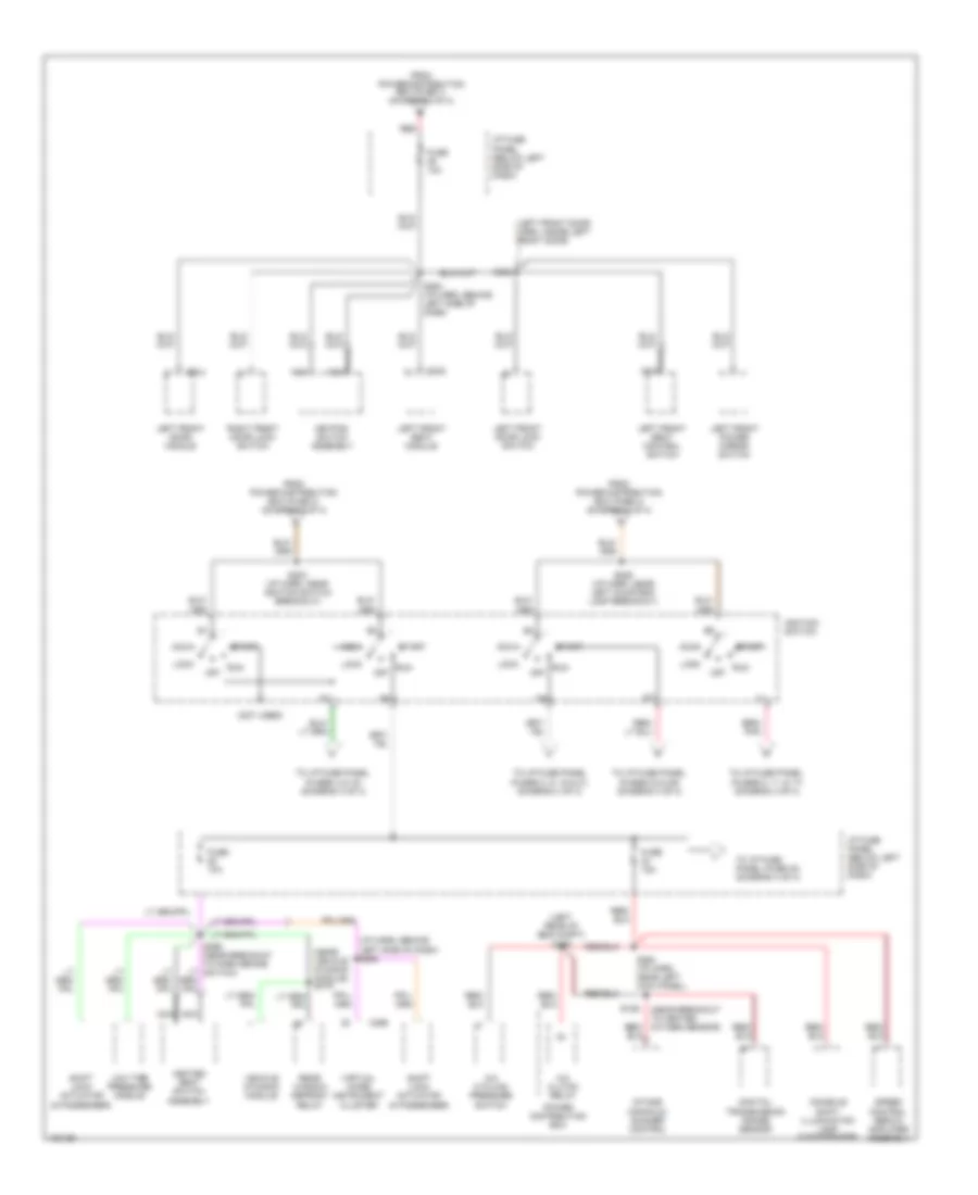
Power Distribution Wiring Diagram (3 of 4) for Lincoln Continental 1998
 https://portal-diagnostov.com/license.html
Automotive Electricians Portal FZCO
Automotive Electricians Portal FZCO
https://portal-diagnostov.com/license.html
https://portal-diagnostov.com/license.html
Automotive Electricians Portal FZCO
Automotive Electricians Portal FZCOList of elements for Power Distribution Wiring Diagram (3 of 4) for Lincoln Continental 1998:
- (i/p harn, behind left side of dash) s268
- (left front door harn, inside left front door)
- (left rear of eng compt) s156
- (near breakout to heated oxygen sensor)
- (near vehicle dynamic module) s419
- (not used)
- A/c clutch relay
- A/c cycling pressure switch
- Acc
- C256
- C342
- C524
- Console shift illumination lamp (5 passenger)
- Digitial transmission range sensor
- From power distribution box (fuse 1) (diagram 2 of 4)
- From power distribution box (fuse 3) (diagram 2 of 4)
- From power distribution box (fuse 4) (diagram 2 of 4)
- Fuse 10a
- Fuse 15a
- Heated seat switch assembly
- I/p fuse panel (below left side of dash)
- Ignition switch
- Intake manifold runner control
- Keypad switch assembly
- Left front door lock switch
- Left front door module
- Left front power mirror switch
- Left front seat control switch
- Left front seat module
- Lock
- Low tire pressure module
- Nca
- Off
- Power distribution box
- Rear window defrost relay
- Red
- Right front door lock switch
- Run
- S129
- S202 (i/p harn, near ignition switch breakout)
- S229 (i/p harn, near left courtesy lamp breakout)
- S254 (i/p harn, behind left side of dash)
- S264 (i/p harn, near left kick panel)
- S502
- Shift lock actuator (5 passenger)
- Shift lock actuator (6 passenger)
- Speed control servo/ amplifier assembly
- Start
- To i/p fuse panel (fuse 40) (diagram 4 of 4)
- To i/p fuse panel (fuses 23 & 29) (diagram 4 of 4)
- To i/p fuse panel (fuses 3, 9, 15 & 21) (diagram 4 of 4)
- To i/p fuse panel (fuses 4 & 16) (diagram 4 of 4)
- To i/p fuse panel (fuses 5, 11, & 17) (diagram 4 of 4)
- Vehicle dynamic module
- Virtual image instrument cluster
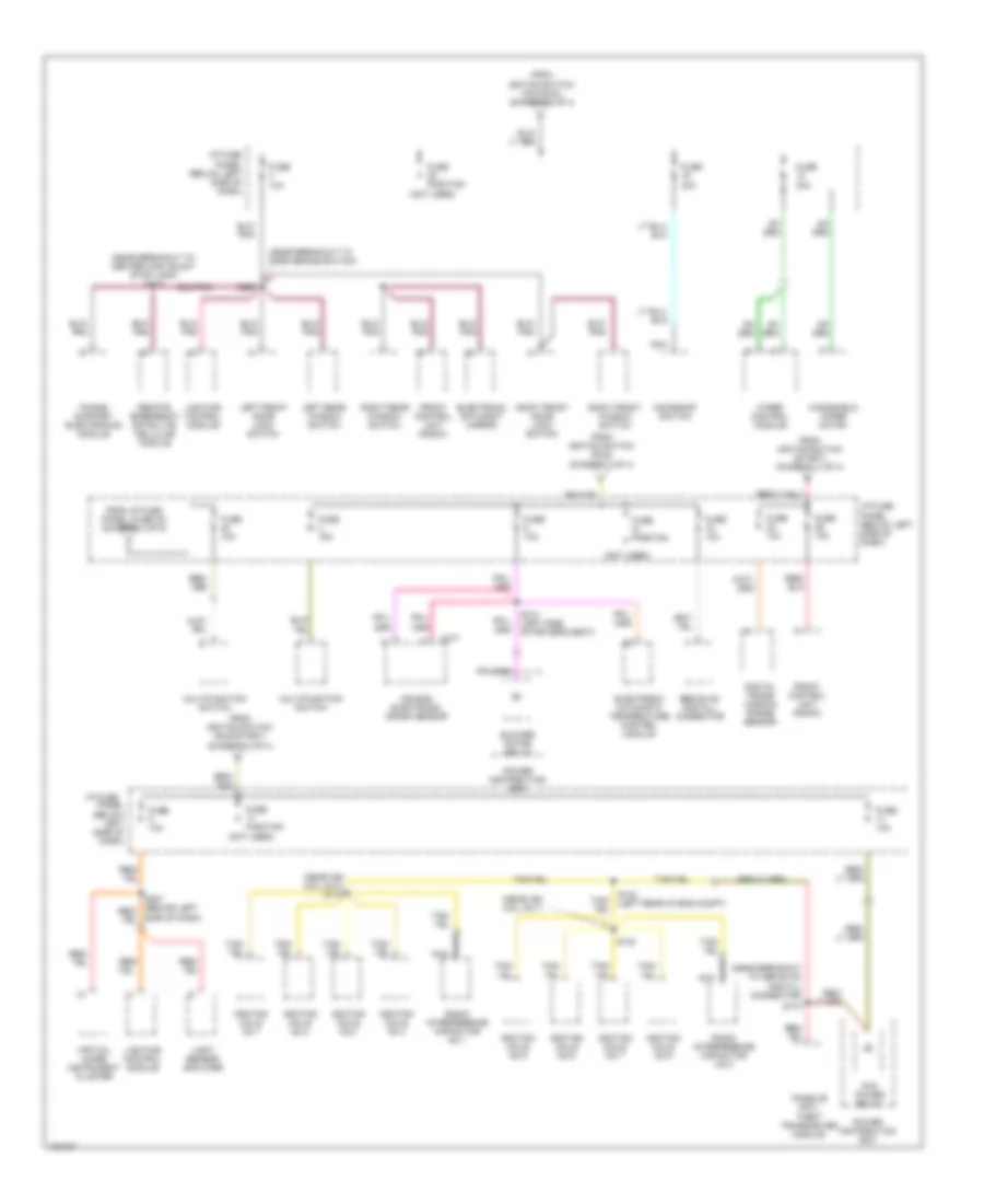
Power Distribution Wiring Diagram (4 of 4) for Lincoln Continental 1998
 https://portal-diagnostov.com/license.html
Automotive Electricians Portal FZCO
Automotive Electricians Portal FZCO
https://portal-diagnostov.com/license.html
https://portal-diagnostov.com/license.html
Automotive Electricians Portal FZCO
Automotive Electricians Portal FZCOList of elements for Power Distribution Wiring Diagram (4 of 4) for Lincoln Continental 1998:
- (near breakout to abs evac and fill connector)
- (near breakout to center high mount stop lamp) s415
- (near breakout to park brake switch)
- (near ign coil no 3) s112
- (near ign coil no 7)
- (not used)
- Air bag electronic crash sensor
- Blower motor relay
- C277
- Digital trans- mission range sensor
- Ebs evac and fill connector
- Electronic automatic temperature control module
- Electronic day/night mirror
- From i/p fuse panel (fuse 34) (diagram 3 of 5)
- From igntion switch (acc/run) (diagram 3 of 4)
- From igntion switch (run) (diagram 3 of 4)
- From igntion switch (run/start) (diagram 3 of 4)
- From igntion switch (start) (diagram 3 of 4)
- Front control unit (radio)
- Fuse 10a
- Fuse 15a
- Fuse 30a
- Fuse position
- I/p fuse
- I/p fuse panel (below left side of dash)
- Ignition coils no 1
- Ignition coils no 2
- Ignition coils no 3
- Ignition coils no 4
- Ignition coils no 5
- Ignition coils no 6
- Ignition coils no 7
- Ignition coils no 8
- Left front door lock switch
- Left rear window switch
- Light sensor/ amplifier
- Lighting control module
- Moonroof switch
- Multifunction switch
- Nca
- Panel (below left side of dash)
- Passive anti- theft transceiver module
- Pcm power relay
- Phone support electronics module
- Power distribution box
- Radio interference capacitor no 1
- Radio interference capacitor no 2
- Red/
- Remote emergency satellite cellular module
- Right front door lock switch
- Right front window switch
- Right rear window switch
- S130
- S132 (left rear of eng compt)
- S170
- S267
- S314 (left side of driver's seat)
- Side of dash)
- Virtual image instrument cluster
- Windshield wiper motor
- Wiper control module

 Čeština
 Dansk
Dansk Deutsch
 Ελληνικά
 English
 English
 Español
 Suomi
Suomi Français
 Français
 עברית
עברית Hrvatski
 Magyar
 Italiano
 한국어
한국어 Nederlands
 Polski
 Português
 Português
 Română
 Русский
 Slovenčina
 Slovenščina
 Svenska
 Türkçe
 中文 (中国)
