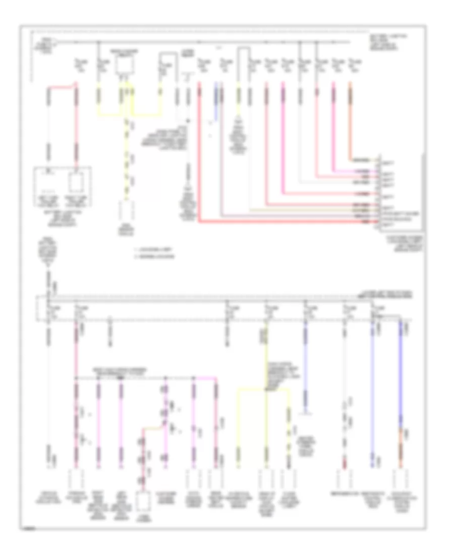
POWER DISTRIBUTION
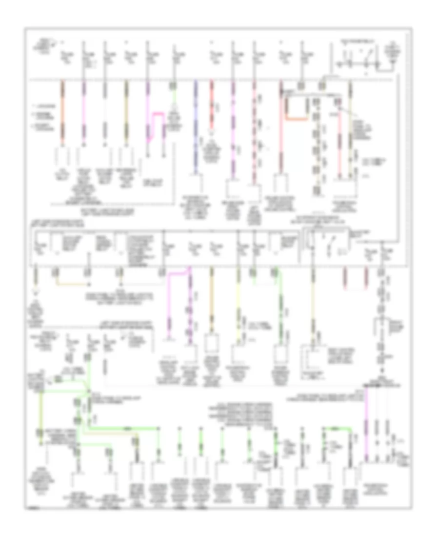
Power Distribution Wiring Diagram (1 of 6) for Lincoln MKT EcoBoost 2014
 https://portal-diagnostov.com/license.html
Automotive Electricians Portal FZCO
Automotive Electricians Portal FZCO
https://portal-diagnostov.com/license.html
https://portal-diagnostov.com/license.html
Automotive Electricians Portal FZCO
Automotive Electricians Portal FZCO
List of elements for Power Distribution Wiring Diagram (1 of 6) for Lincoln MKT EcoBoost 2014:
- (diagram 6 of 6)
- (left side of engine compt) battery junction box (bjb)
- (not used)
- (passenger's cushion wiring harness, near breakout to dual climate controlled seat module) s322
- (passenger's cushion wiring harness, near breakout to passenger's seat rear height motor) (limousine/livery) s324
- (right front of center console) g200
- (right rear seat c3133 (left side) wiring harness, near breakout to left rear lumbar adjust switch) s333
- Aft seat relay
- Anti-lock brake system (abs) module
- Battery
- Battery junction box (bjb) (left side of engine compt)
- Blower motor relay
- Brake pedal position (bpp) switch
- Breakout to c3249) s328
- C144
- C1467b
- C1617a
- C1617b
- C1617c
- C1617d
- C210
- C211
- C214
- C219
- C3049
- C3050
- C3136
- C3190a
- C3265a
- C3304b
- C3309
- C3365a
- C3368
- C340
- C341a
- C3519
- C4174a
- C922
- Driver seat module (dsm)
- Dual climate controlled seat module (dcsm)
- Except limousine
- Except long console
- Forward seat relay
- Front console power point
- Fuse 10a
- Fuse 15a
- Fuse 20a
- Fuse 30a
- Fuse 40a
- Fuse 50a
- Fuse link a (10 ga- red)
- Fuse link b (10 ga- red)
- Fuse n/a
- G103 (left front of engine compt)
- G104 (3.5l: rear of engine) (3.7l: top rear of engine)
- G200 (right front of center console)
- G401 (left rear of cargo area)
- Generator
- Generator current sensor
- Hearse/limousine
- High current battery junction box (bjb) (left side of engine compt)
- High fan control (hfc) relay
- Left headlamp assembly
- Liftgate/ trunk module (ltm)
- Limousine
- Limousine/livery
- Long console
- Low fan control (lfc) relay
- Mega fuse 1 100a
- Mega fuse 2 60a
- Mega fuse 4 100a
- Nca
- Parking lamp trailer tow relay
- Passenger side front seat control switch
- Power steering control module (pscm)
- Rear console power point
- Rear dual climate controlled seat module (dcsm)
- Rear heated seat module
- Rear power point
- Rear window defrost relay
- Rear wiper motor assembly
- Red
- Right headlamp assembly
- Roof opening panel module (w/ panoramic roof) sunshade motor (w/ vista roof)
- S127 (battery wiring harness, near breakout to starter motor)
- S128 (battery wiring harness, near breakout to c140)
- S129 (battery wiring harness, near breakout to c140)
- S300
- S406
- Starter motor
- Starter relay
- Third row power seat relay
- To body control module (bcm) (diagram 3 of 6)
- To fuse 62 (diagram 2 of 6)
- To fuse 63 c
- Trailer brake control (tbc) module
- Wiper relay
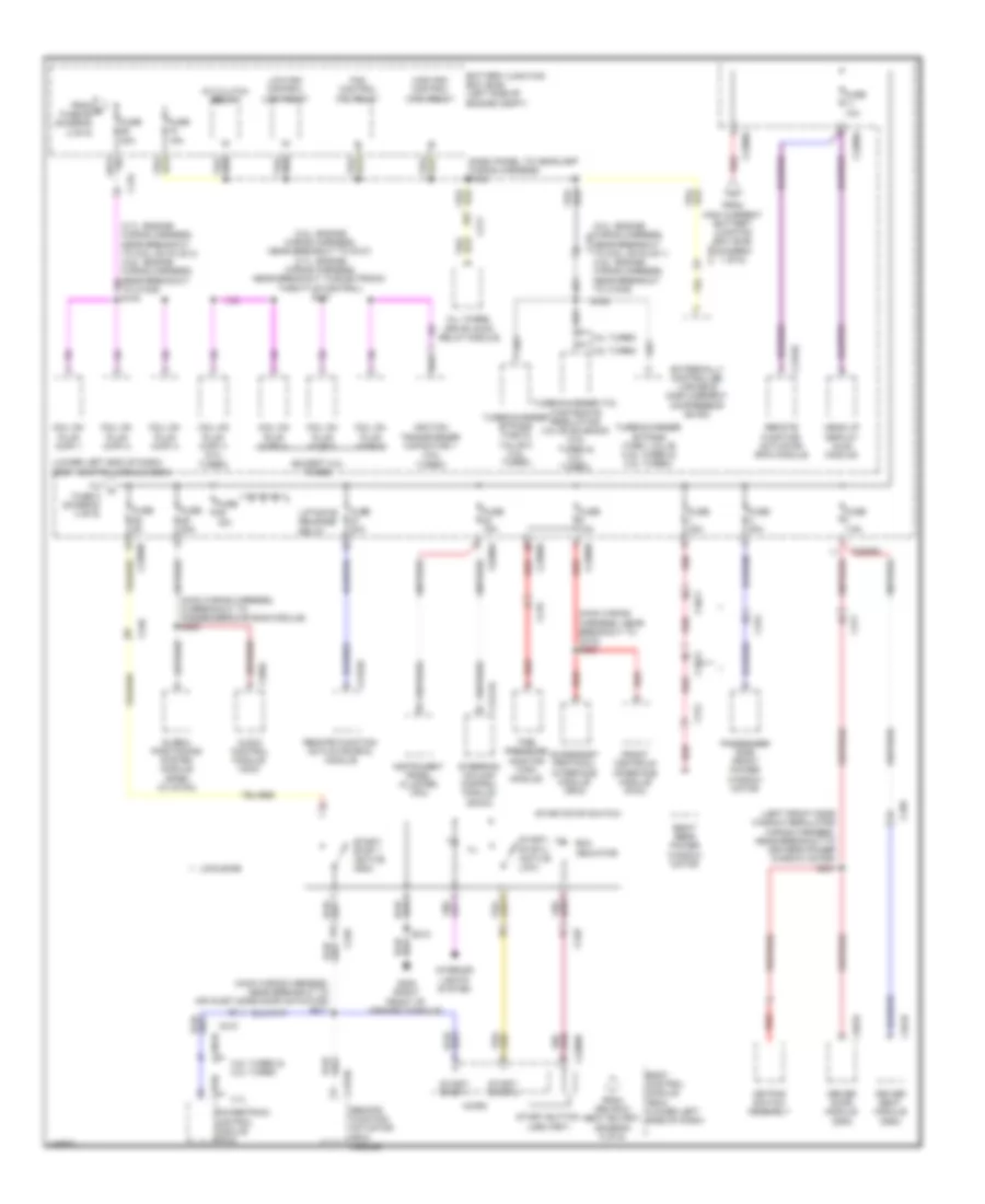
Power Distribution Wiring Diagram (2 of 6) for Lincoln MKT EcoBoost 2014
 https://portal-diagnostov.com/license.html
Automotive Electricians Portal FZCO
Automotive Electricians Portal FZCO
https://portal-diagnostov.com/license.html
https://portal-diagnostov.com/license.html
Automotive Electricians Portal FZCO
Automotive Electricians Portal FZCOList of elements for Power Distribution Wiring Diagram (2 of 6) for Lincoln MKT EcoBoost 2014:
- (2.0l: engine wiring harness, near breakout to coil on plug 1) (3.7l: engine wiring harness, near breakout to coil on plug 3) (3.5l: engine wiring harness, near breakout to c1045) s146
- (battery wiring harness, near breakout to starter motor) s120
- (dash panel to headlamp wiring harness)
- (left side of engine compt) battery junction box (bjb)
- 2.0l turbo
- 3.5l turbo
- 3.5l turbo & 2.0l turbo
- 3.5l turbo & 2.0l turbo 3.7l
- 3.7l
- A/c clutch relay
- Anti-lock brake system (abs) module
- Auxiliary blower motor relay
- Battery junction box (bjb) (left side of engine compt)
- Blower motor relay
- Body control module (bcm) (lower left end of dash)
- C134
- C1381b
- C139
- C140
- C144
- C1467a
- C175b
- C210
- C211
- C214
- C2280f
- C260
- C311
- C313
- C315
- C3309
- C3411
- C3413
- C3519
- Cruise control module (ccm) (w/ adaptive cruise control)
- Driver side front power window motor
- Evaporative emission (evap) canister vent valve (3.5l turbo & 2.0l turbo)
- Evaporative emission (evap) canister vent valve (3.7l)
- Evaporative emission (evap) purge valve
- Except
- Except 2.0l turbo
- Except 3.7l
- From fuse 9 b (diagram 1 of 6)
- From pcm power d relay (diagram 2 of 6)
- From splice s113 (diagram 2 of 6)
- Front power point
- Fuel pump (fp) relay
- Fuse 10a
- Fuse 20a
- Fuse 30a
- Fuse 30a 40a
- Fuse 5a
- Fuse n/a
- G200 (right front of center console)
- Headlamp control module (hcm) (w/ adaptive headlamps)
- Hearse/
- Heated oxygen sensor (ho2s) 12 (2.0l turbo)
- Heated oxygen sensor (ho2s) 12 (3.5l turbo)
- Heated oxygen sensor (ho2s) 12 (3.7l)
- Heated oxygen sensor (ho2s) 22 (3.5l turbo)
- Heated oxygen sensor (ho2s) 22 (3.7l)
- Left rear power window motor
- Limousine
- Mass air flow/ intake air temperature (maf/iat) sensor (3.7l)
- Nca
- Pcm power relay
- Power steering control module (pscm)
- Powertrain control module (pcm)
- Rear window defrost relay
- Red
- Reversing lamps trailer tow relay
- Run/start (fet)
- Run/start relay
- S114 (dash panel to headlamp junction wiring harness, near breakout to c134)
- S132
- S142 (dash panel to headlamp junction wiring harness, near breakout to battery junction box)
- S300
- To battery junction box (bjb) (diagram 2 of 6)
- To body control module (bcm) (diagram 6 of 6)
- To dc/ac inverter module (diagram 5 of 6)
- To fuse 68 (diagram 3 of 6)
- To fuse 71 (diagram 2 of 6)
- Universal heated oxygen sensor (ho2s)
- Universal heated oxygen sensor (ho2s) 11
- Used) (not
- Vacuum pump cutoff relay (limousine) trailer tow battery charge relay (except limousine)
- Variable camshaft timing 11 (vct11) solenoid
- Variable camshaft timing 12 (vct12) solenoid (except 3.5l turbo)
- Variable camshaft timing 21 (vct21) solenoid (except 2.0l turbo)
- Variable camshaft timing 22 (vct22) solenoid (3.7l)
- Wiring harness)
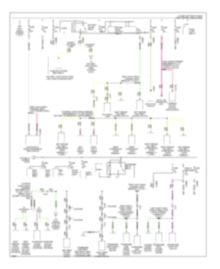
Power Distribution Wiring Diagram (3 of 6) for Lincoln MKT EcoBoost 2014
 https://portal-diagnostov.com/license.html
Automotive Electricians Portal FZCO
Automotive Electricians Portal FZCO
https://portal-diagnostov.com/license.html
https://portal-diagnostov.com/license.html
Automotive Electricians Portal FZCO
Automotive Electricians Portal FZCOList of elements for Power Distribution Wiring Diagram (3 of 6) for Lincoln MKT EcoBoost 2014:
- (2.0l: engine wiring harness, near breakout to coil on plug 1) c134
- (3.5l: engine wiring harness, near breakout to c1045)
- (3.5l: engine wiring harness, near breakout to g107) (3.7l: engine wiring harness, near breakout to electronic throttle control) s147
- (3.7l: engine wiring harness, near breakout to coil on plug 3) (3.5l: engine wiring harness, near breakout to c1045) s140
- (dash panel to headlamp wiring harness) s138
- (except 2.0l turbo)
- (left front door window regulator wiring harness, near breakout to driver's power window motor) s501
- (lower left end of dash) body control module (bcm)
- (main wiring harness, in breakout to passenger's air bag module) s202
- (main wiring harness, near breakout to air inlet mode door actuator) s211
- (main wiring harness, near breakout to c210) s200
- 2.0l turbo
- 3.5l turbo
- 3.5l turbo & 2.0l turbo
- 3.7l
- A/c clutch relay
- Accessory protocol interface module (apim)
- All wheel drive (awd) relay module
- Audio control module (acm)
- Battery junction box (bjb) (left side of engine compt)
- Body control module (bcm) (lower left side of dash)
- C134
- C1381b
- C144
- C175b
- C210
- C211
- C2153c
- C219
- C2280a
- C2280b
- C2280d
- C2280g
- C240a
- C2414a
- C248
- C311
- C312
- C314
- C339
- C3411
- C3413
- C341b
- C501b
- Coil on plug (cop) 1
- Coil on plug (cop) 2
- Coil on plug (cop) 3
- Coil on plug (cop) 4
- Coil on plug (cop) 4 (2.0l turbo)
- Coil on plug (cop) 5
- Coil on plug (cop) 6
- Driver door module (ddm)
- Driver seat module (dsm)
- Externally controlled variable displacement compressor (evdc)
- Fan control (fc) relay
- From 3rd row seat en (fet) (diagram 5 of 6)
- From e fuse 69 (diagram 2 of 6)
- From high current battery junction box (bjb) (diagram 1 of 6)
- Front controls interface module (fcim)
- Fuse 10a
- Fuse 15a
- Fuse 20a
- Fuse 30a
- Fuse 5a
- Fuse 7.5a
- G200 (right front of center console)
- Global positioning system module (gpsm) (w/ sync)
- Head up display (hud) module
- High fan control (hfc) relay
- Ignition transformer capacitor 1 (3.5l turbo)
- Ill
- Instrument panel cluster (ipc)
- Interior lights system
- Keypad switch assembly
- Liftgate release relay
- Limousine
- Low fan control (lfc) relay
- Micro
- Passenger side front power window motor
- Powertrain control module (pcm)
- Red
- Remote function actuator (rfa) module
- Right rear power window motor
- Run indicator
- S150
- S212
- Start button (led) (fet)
- Start/ stop 1
- Start/ stop 1 (active high)
- Start/ stop 2
- Start/ stop 2 (active low)
- Start/stop switch
- Steering column control module (sccm)
- Tire pressure monitor (tpm) module
- To fuse 5 (diagram 4 of 6)
- Turbocharger (tc) wastegate regulating valve solenoid (3.5l turbo & 2.0l turbo)
- Turbocharger bypass (tcby) valve (3.5l turbo & 2.0l turbo)
- Turbocharger bypass (tcby2) valve 2 (3.5l turbo)
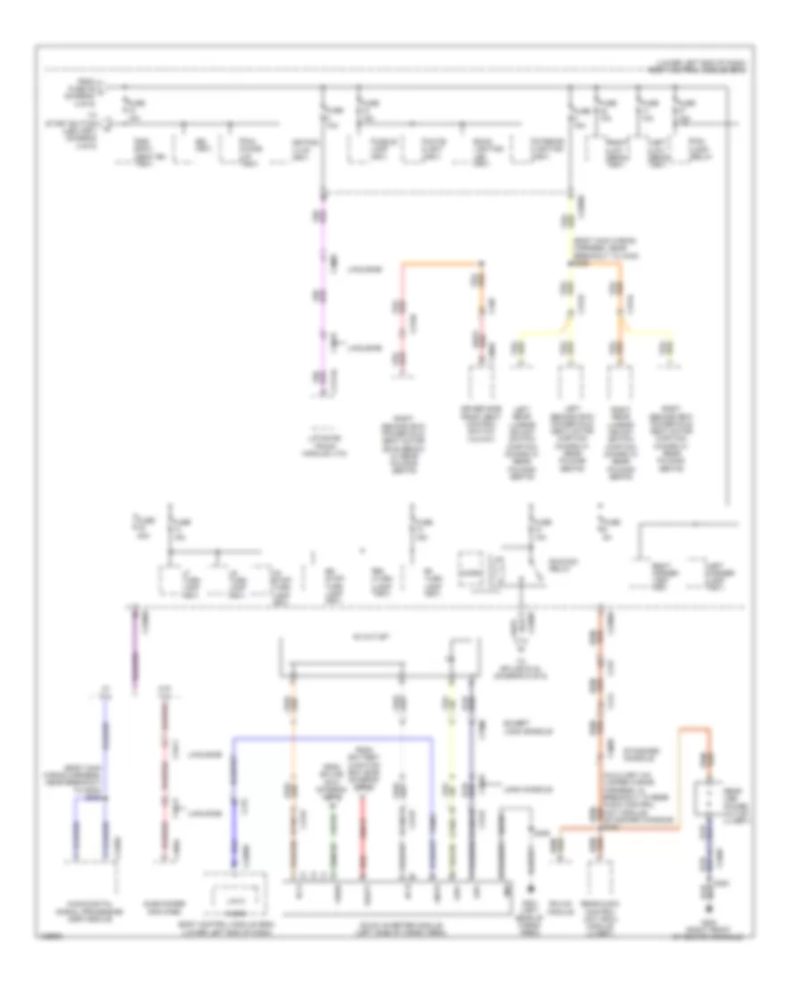
Power Distribution Wiring Diagram (4 of 6) for Lincoln MKT EcoBoost 2014
 https://portal-diagnostov.com/license.html
Automotive Electricians Portal FZCO
Automotive Electricians Portal FZCO
https://portal-diagnostov.com/license.html
https://portal-diagnostov.com/license.html
Automotive Electricians Portal FZCO
Automotive Electricians Portal FZCOList of elements for Power Distribution Wiring Diagram (4 of 6) for Lincoln MKT EcoBoost 2014:
- (body main wiring harness, near breakout to c311) s307
- (body main wiring harness, near breakout to c311) s310
- (body main wiring harness, near joint connector 30) s401
- (interior lamps wiring harness, near breakout to left second row seat interior/map lamps assembly) s902
- (left front door window regulator wiring harness, in breakout to c311) s500
- (lower left end of dash) body control module (bcm)
- (main wiring harness, near breakout to steering column control module) s201
- (not used)
- (right front door window regulator wiring harness, in breakout to c312) s602
- Accessory delay relay
- All lock/ unlock relay
- Audio digital signal processing (dsp) module
- Battery junction box (bjb) (left side of engine compt)
- Battery saver relay
- C215
- C219
- C2280a
- C2280b
- C2280d
- C2280f
- C228a
- C2414b
- C311
- C312
- C313
- C314
- C3309
- C3411
- C3413
- C3519
- C4326c
- Circuit breaker 30a
- Data link connector (dlc)
- Datc hvac module
- Driver door unlock relay
- Driver side door lock switch
- Driver side front power window motor
- Except limousine/ livery
- From fuse 26 (diagram 3 of 6)
- Front interior/map lamps assembly
- Fuse 10a
- Fuse 15a
- Fuse 20a
- Glove box lamp
- Horn relay
- Left high beam (fet)
- Left rear power window motor
- Left second row seat control switch
- Left second row seat interior/map lamps assembly
- Left second row seat interior/map lamps assembly 2 (livery)
- Left vanity mirror lamp
- Limousine
- Limousine/ livery
- Master window control switch
- Micro
- Park lamp relay
- Passenger side door lock switch
- Passenger side front power window motor
- Passenger side front redundant seat adjust switch (limousine/livery)
- Passenger side window control switch
- Rear interior/map lamps assembly
- Red
- Rev lp (fet)
- Right high beam (fet)
- Right rear power window motor
- Right second row seat control switch
- Right second row seat interior/map lamps assembly
- Right second row seat interior/map lamps assembly 2 (livery)
- Right vanity mirror lamp
- Roof opening panel control switch (except limousine)
- Roof opening panel module (except limousine)
- Steering column control module (sccm)
- Stop/ chmsl (fet)
- Sunshade motor (except limousine)
- Sunshade switch (except limousine)
- Third row power seat relay
- To battery junction box (bjb) (diagram 6 of 6)
- To dc/ac inverter module (diagram 5 of 6)
- To fuse 18 (diagram 5 of 6)
- Used) (not
- W/ panoramic roof
- W/ vista roof
Power Distribution Wiring Diagram (5 of 6) for Lincoln MKT EcoBoost 2014
 https://portal-diagnostov.com/license.html
Automotive Electricians Portal FZCO
Automotive Electricians Portal FZCO
https://portal-diagnostov.com/license.html
https://portal-diagnostov.com/license.html
Automotive Electricians Portal FZCO
Automotive Electricians Portal FZCOList of elements for Power Distribution Wiring Diagram (5 of 6) for Lincoln MKT EcoBoost 2014:
- (body main wiring harness, near breakout to c340) s308
- (body main wiring harness, near breakout to g300) s309
- (lower left end of dash) body control module (bcm)
- 3rd row seat en (fet)
- Ac outlet
- Ac-a
- Ac-b
- Audio digital signal processing (dsp) module
- Back- lighting led (fet)
- Body control module (bcm) (lower left end of dash)
- Bsi (fet)
- C214
- C215
- C2280b
- C2280d
- C2280f
- C3049
- C3133
- C3134
- C3136
- C3137
- C3309
- C3368
- C339
- C3411
- C3413
- C3519
- C360a
- C4174a
- C4326c
- C466a
- Cbp32
- Dc/ac inverter module (left side of cargo area)
- Driver side front seat control switch (12-way)
- Except long console
- Fog lamp relay
- From battery junction box (bjb) (diagram 2 of 6)
- From fuse 39 j (diagram 4 of 6)
- From splice s310 (diagram 4 of 6)
- Fuse 10a
- Fuse 15a
- Fuse 20a
- Fuse 5a
- G200 (right front of center console)
- G401 (left rear of cargo area)
- Gd349
- Gnd
- Hya01
- Hya02
- Interior lighting (fet)
- Keypad illum (fet)
- Led+
- Led-
- Left corner lamp (fet)
- Left low beam (fet)
- Left rear lumbar adjust switch (captain chairs w/ rear folding seats)
- Left second row power fold seat motor (captain chairs w/ rear folding seats)
- Lf turn lamp (fet)
- Liftgate/ trunk module (ltm)
- Limousine
- Lin 01
- Long console
- Lr stop/ turn lamp (fet)
- Lr turn lamp (fet)
- Lya03
- Micro
- Pcm wake up (fet)
- Puddle lamp (fet)
- Rear audio control unit (rcu) module (livery)
- Rear usb power outlet (livery)
- Red
- Rf turn lamp (fet)
- Rhvac module
- Right corner lamp (fet)
- Right low beam (fet)
- Right rear lumbar adjust switch (captain chairs w/ rear folding seats)
- Right second row power fold seat motor (60/40 bench w/ rear folding seats)
- Right second row power fold seat motor (captain chairs w/ rear folding seats)
- Rr stop/ turn lamp (fet)
- Rr turn lamp (fet)
- Run/acc relay
- Rya03
- S300
- S406
- Sbb17
- Standard console
- Subwoofer amplifier
- To splice s144 (diagram 6 of 6)
- To start button (led) (fet) (diagram 3 of 6)
- Unit module) (standard console) s335
- Vbatt
- Vdn01
- Vpwr
- W/ thx
- W/o thx
- White light (fet)
Power Distribution Wiring Diagram (6 of 6) for Lincoln MKT EcoBoost 2014
 https://portal-diagnostov.com/license.html
Automotive Electricians Portal FZCO
Automotive Electricians Portal FZCO
https://portal-diagnostov.com/license.html
https://portal-diagnostov.com/license.html
Automotive Electricians Portal FZCO
Automotive Electricians Portal FZCOList of elements for Power Distribution Wiring Diagram (6 of 6) for Lincoln MKT EcoBoost 2014:
- (body main wiring harness, near breakout to c340) s311
- (lower left end of dash) body control module (bcm)
- (main wiring harness, near breakout to glove box lamp) (except base) s203
- (not used)
- Auto- dimming interior mirror
- Battery junction box (bjb) (left side of engine compt)
- C211
- C214
- C219
- C2280b
- C2280d
- C2280e
- C3049
- C3050
- C310a
- C3136
- C3304b
- C3309
- C3411
- C3413
- C3519
- C410
- C4396b
- C913
- C919
- Customer access (hearse)
- Customer access (limousine/livery) (left rear of engine compt)
- Floor shifter (limousine/ livery)
- From battery junction box (bjb) (diagram 2 of 6)
- From body control module (bcm) (diagram 4 of 6)
- From body control module (bcm) (diagram 5 of 6)
- From fuse 78 c (diagram 1 of 6)
- Fuse 10a
- Fuse 15a
- Fuse 20a
- Fuse 30a
- Fuse 40a
- Fuse 50a
- Fuse 5a
- Fuse 7.5a
- Head up display (hud) module (except base)
- Hearse/limousine
- Heated steering wheel module (hswm)
- In-vehicle temperature/ humidity sensor
- Left rear side obstacle detection (sod) sensor
- Left turn trailer tow relay
- Limousine/livery
- Nca
- Occupant classification system module (ocsm)
- Parking aid module (pam)
- Rain sensor module
- Rear heated seat module
- Rear washer relay
- Red
- Refrigerator
- Restraints control module (rcm)
- Right rear side obstacle detection (sod) sensor
- Right turn trailer tow relay
- S144 (dash panel to headlamp junction wiring harness, near breakout to battery junction box)
- Vbatt
- Vehicle dynamics module (vdm)
- Video camera
- Vpwr (batt saver)
- Vpwr (run/acc)
- Wiper relay

 Čeština
 Dansk
Dansk Deutsch
 Ελληνικά
 English
 English
 Español
 Suomi
Suomi Français
 Français
 עברית
עברית Hrvatski
 Magyar
 Italiano
 한국어
한국어 Nederlands
 Polski
 Português
 Português
 Română
 Русский
 Slovenčina
 Slovenščina
 Svenska
 Türkçe
 中文 (中国)
