ENGINE PERFORMANCE
3.0L
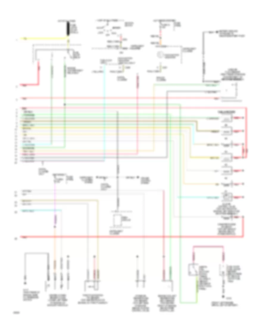
3.0L, Engine Performance Wiring Diagrams (1 of 2) for Ford Aerostar 1994
 https://portal-diagnostov.com/license.html
Automotive Electricians Portal FZCO
Automotive Electricians Portal FZCO
https://portal-diagnostov.com/license.html
https://portal-diagnostov.com/license.html
Automotive Electricians Portal FZCO
Automotive Electricians Portal FZCO
List of elements for 3.0L, Engine Performance Wiring Diagrams (1 of 2) for Ford Aerostar 1994:
- 3-4/4-3 shift solenoid
- A4ld automatic transmission
- Accs
- Air conditioning
- Air conditioning system
- Boo
- Brake on/off switch (behind steering column)
- C256
- Canp
- Coil output
- Cse gnd
- Data (+)
- Data (-)
- Data link connector (right rear corner of engine compartment)
- Digital cluster only
- Distributor
- Dol
- Ect
- Engine compartment relay box
- Fpm
- Fuse 15a
- Fuse panel
- G100 (front left fender apron, left of battery)
- G206 (behind center of i/p, below right side of radio)
- H2os
- Hot at all times
- Hot in start or run
- Iac
- Iat
- Idm
- Ign gnd
- Ign pwr
- Ignition coil
- Ignition control module (icm) (center of right fender apron, near air cleaner)
- Inj 1
- Inj 2
- Inj 3
- Inj 4
- Inj 5
- Inj 6
- Instrument cluster
- Kapwr
- Maf
- Maf rtn
- Nca
- Pcm power relay
- Pcm power relay diode
- Pip
- Pnk
- Pnp
- Power distribution system
- Powertrain control module (pcm) (top left side of safety wall, left side of brake master cylinder)
- Psom (+)
- Psom (-)
- Pwr gnd
- Radio noise capacitor (top left rear of engine, near ignition coil)
- Red
- Sig rtn
- Spout
- Spout check connector (left rear of engine compartment, tape to engine control sensor harness, near master cylinder)
- Ss 3/4
- Starting/ charging system
- Sti
- Sti connector (right rear corner of engine compartment)
- Sto/mil
- System
- Tan
- Tcc
- Torque converter clutch solenoid
- Vpwr
- Vref
- Wac
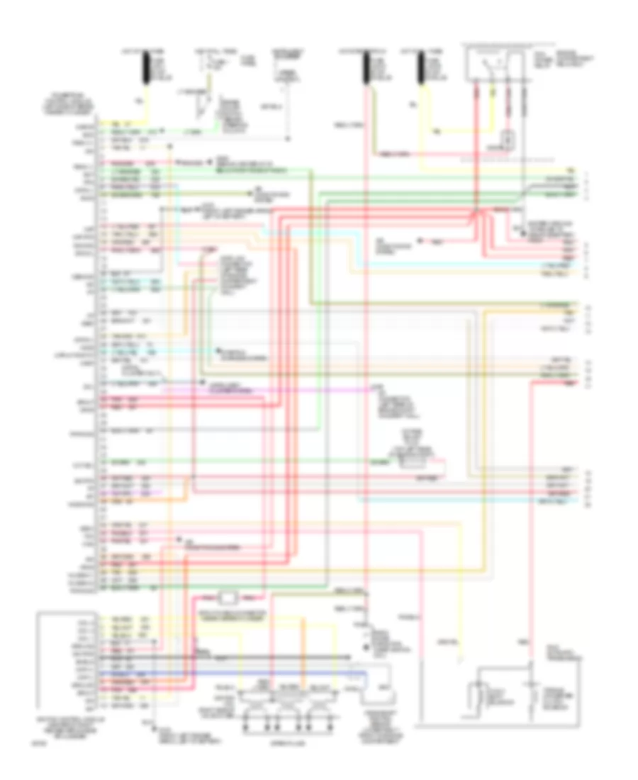
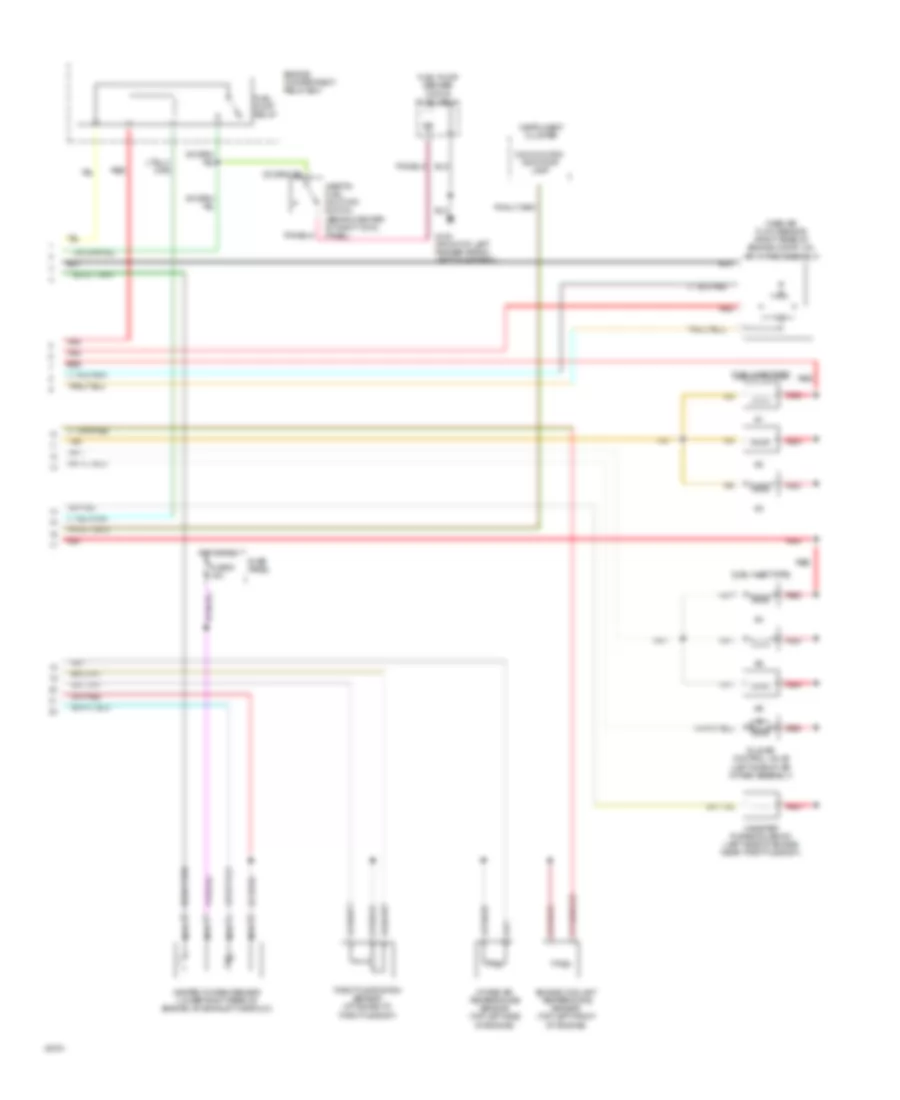
3.0L, Engine Performance Wiring Diagrams (2 of 2) for Ford Aerostar 1994
 https://portal-diagnostov.com/license.html
Automotive Electricians Portal FZCO
Automotive Electricians Portal FZCO
https://portal-diagnostov.com/license.html
https://portal-diagnostov.com/license.html
Automotive Electricians Portal FZCO
Automotive Electricians Portal FZCOList of elements for 3.0L, Engine Performance Wiring Diagrams (2 of 2) for Ford Aerostar 1994:
- (front left fender apron, left of battery)
- Acc
- Analog cluster
- C251
- C255
- C256
- C284
- Canister purge solenoid (top left side of engine, below intake manifold)
- Cruise control system
- Digital cluster
- Digital cluster only
- Engine compartment relay box
- Engine coolant temperature (ect) sensor (top center front of engine, above water pump pulley)
- Fuel flow input
- Fuel injectors
- Fuel pump relay
- Fuel pump/ fuel gauge sender (below rear of vehicle, top of fuel tank)
- Fuse 18 15a
- Fuse 5 15a
- Fuse panel
- G100
- G117 (right rear of engine, near oil pressure switch)
- Heated oxygen sensor (ho2s) (lower left rear of engine, on exhaust manifold)
- Hot at all times
- Hot in run
- Hot in run or start
- Idle air control valve (top left front of engine, left side of air air intake assembly)
- Ign
- Ignition switch
- Inertia fuel shut-off switch (opens on impact) (behind center of right cowl panel)
- Instrument cluster
- Instrument clusters system
- Intake air temperature (iat) sensor (top left side of engine, behind idle air control valve)
- Lock
- Malfunction indicator
- Malfunction indicator lamp (mil) input
- Mass air flow sensor (right rear of engine compartment, on air intake assembly)
- Nca
- Off
- Psom module
- Red
- Run
- Start
- Tan
- Throttle position (tp) sensor (top center front of engine, on throttle body)
4.0L
4.0L, Engine Performance Wiring Diagrams (1 of 2) for Ford Aerostar 1994
 https://portal-diagnostov.com/license.html
Automotive Electricians Portal FZCO
Automotive Electricians Portal FZCO
https://portal-diagnostov.com/license.html
https://portal-diagnostov.com/license.html
Automotive Electricians Portal FZCO
Automotive Electricians Portal FZCOList of elements for 4.0L, Engine Performance Wiring Diagrams (1 of 2) for Ford Aerostar 1994:
- 3-4/4-3 shift solenoid
- A4ld automatic transmission
- Accs
- Air conditioning system
- Boo
- Brake on/off switch (behind steering column)
- C198
- C199
- Canp
- Ckp (+)
- Ckp (-)
- Coil 1
- Coil 2
- Coil 3
- Cpp m/t-pnp a/t
- Crankshaft position sensor (lower right front of engine compartment)
- Cse gnd
- Data (+)
- Data (-)
- Data link connector (left rear of engine compartment on safety wall)
- Digital cluster only
- Diode
- Dol
- Ect
- Engine compartment relay box
- Fpm
- Fuse 1 15a
- Fuse panel
- G100 (front left fender apron, left of battery)
- G206 (behind center of i/p, below right side of radio)
- Ground
- Ho2s
- Ho2s gnd
- Hot at all times
- Hot start or run
- Iac
- Iat
- Idm
- Ign gnd
- Ign pwr
- Ignition coil (right side of valve cover)
- Ignition control module (center of right fender apron near air cleaner)
- Inj bank 1
- Inj bank 2
- Instrument cluster
- Instrument cluster system
- Kapwr
- Maf
- Maf rtn
- Nca
- Oct adj
- Octane adjust plug (top left rear of engine compt)
- Pcm power relay
- Pip
- Pnk
- Powertrain control module (left side of brake master cylinder)
- Psom (+)
- Psom (-)
- Pwr gnd
- Radio noise capacitor (near ignition coil)
- Red
- Shield
- Sig rtn
- Spark plugs
- Speed output
- Spout
- Spout check connector (near master cylinder)
- Ss3/4
- Starting charging system
- Sti
- Sti connector (left rear of engine compt on safety wall)
- Sto/mil
- Tan
- Tcc
- Torque converter clutch solenoid
- Vpwr
- Vref
- Wac
4.0L, Engine Performance Wiring Diagrams (2 of 2) for Ford Aerostar 1994
 https://portal-diagnostov.com/license.html
Automotive Electricians Portal FZCO
Automotive Electricians Portal FZCO
https://portal-diagnostov.com/license.html
https://portal-diagnostov.com/license.html
Automotive Electricians Portal FZCO
Automotive Electricians Portal FZCOList of elements for 4.0L, Engine Performance Wiring Diagrams (2 of 2) for Ford Aerostar 1994:
- Canister purge solenoid (left side of engine near throttle body)
- Engine compartment relay box
- Engine coolant temperature sensor (top left front of engine)
- Fuel injectors
- Fuel pump relay
- Fuel pump/ sender (top of fuel tank)
- Fuse 5 15a
- Fuse panel
- G100 (front of left fender apron left of battery)
- Heated oxygen sensor (lower right rear of engine, on exhaust manifold)
- Hot in run
- Idle air control valve (left side of air intake assembly)
- Inertia fuel shut-off switch (behind center of right cowl panel)
- Instrument cluster
- Intake air temperature sensor (top left side of engine)
- Malfunction indicator lamp
- Mass air flow sensor (right rear of engine compt, on air intake assembly)
- Nca
- Red
- Tan
- Throttle position sensor (attached to throttle body)

 Čeština
 Dansk
Dansk Deutsch
 Ελληνικά
 English
 English
 Español
 Suomi
Suomi Français
 Français
 עברית
עברית Hrvatski
 Magyar
 Italiano
 한국어
한국어 Nederlands
 Polski
 Português
 Português
 Română
 Русский
 Slovenčina
 Slovenščina
 Svenska
 Türkçe
 中文 (中国)
