ENGINE PERFORMANCE
4.0L
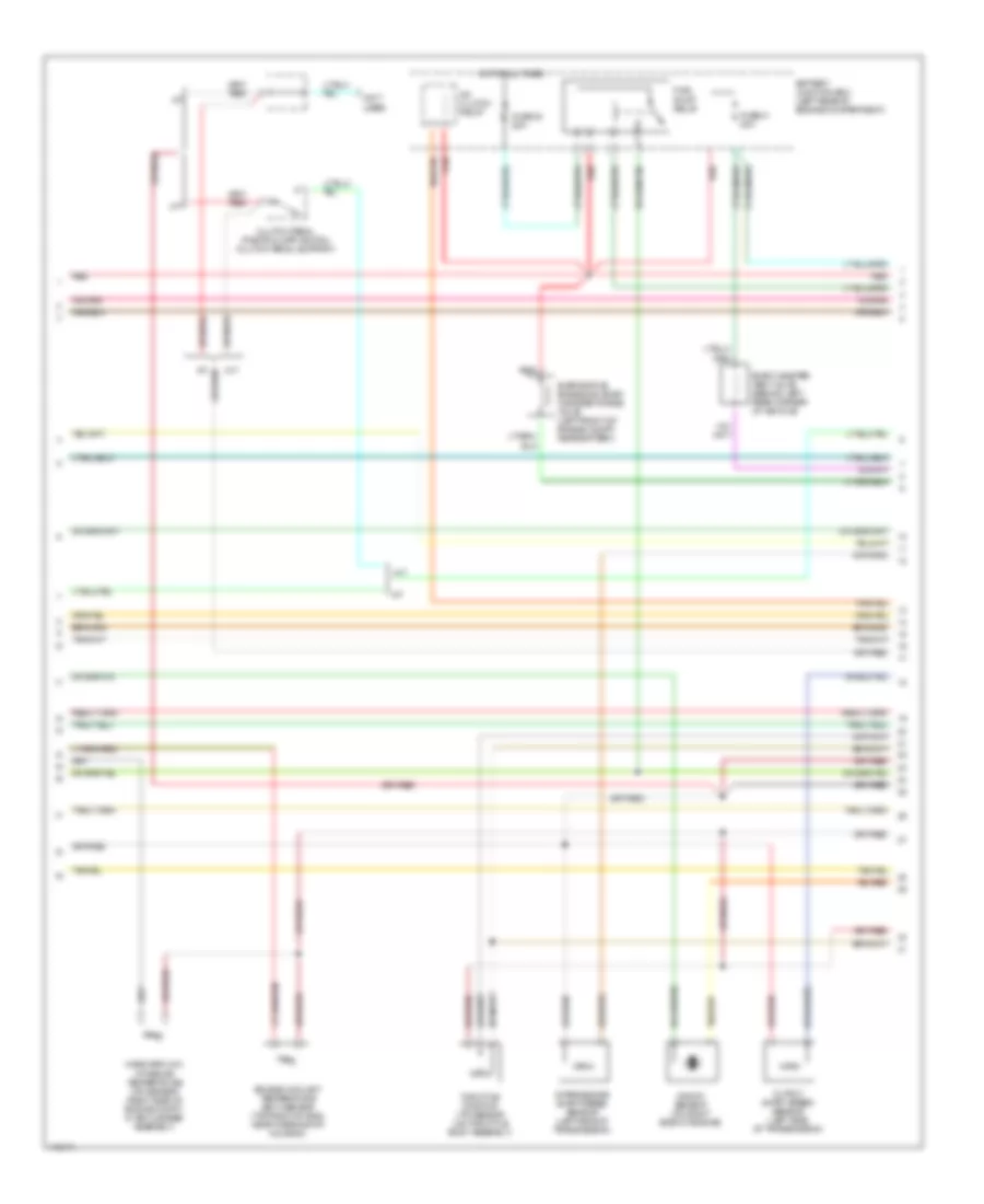
4.0L, Engine Performance Wiring Diagram (1 of 4) for Mazda B4000 Dual Sport 2003
 https://portal-diagnostov.com/license.html
Automotive Electricians Portal FZCO
Automotive Electricians Portal FZCO
https://portal-diagnostov.com/license.html
https://portal-diagnostov.com/license.html
Automotive Electricians Portal FZCO
Automotive Electricians Portal FZCO
List of elements for 4.0L, Engine Performance Wiring Diagram (1 of 4) for Mazda B4000 Dual Sport 2003:
- (behind left headlight)
- (fastened to bottom of dash, near steering column) data link connector (dlc)
- Air conditioning system
- Anti-theft system
- Battery junction box (left rear of engine compartment)
- C209
- C215
- Central junction box (behind left side of dash)
- Crankshaft position (ckp) sensor (on lower front of engine)
- Digital transmission range sensor (left side of transmission)
- Fuse 25a
- Fuse 7 30a
- Fuse 7.5a
- G2 (rear of engine compt)
- Hot at all times
- Hot in run or start
- Ignition coil (on rear of eng)
- Ignition transformer capacitor 1
- Instrument cluster
- Malfunction indicator lamp (mil)
- Pcm power diode
- Pcm power relay
- Powertrain control module (pcm) (right rear of engine compartment, through firewall)
- Red
- Starting/ charging system
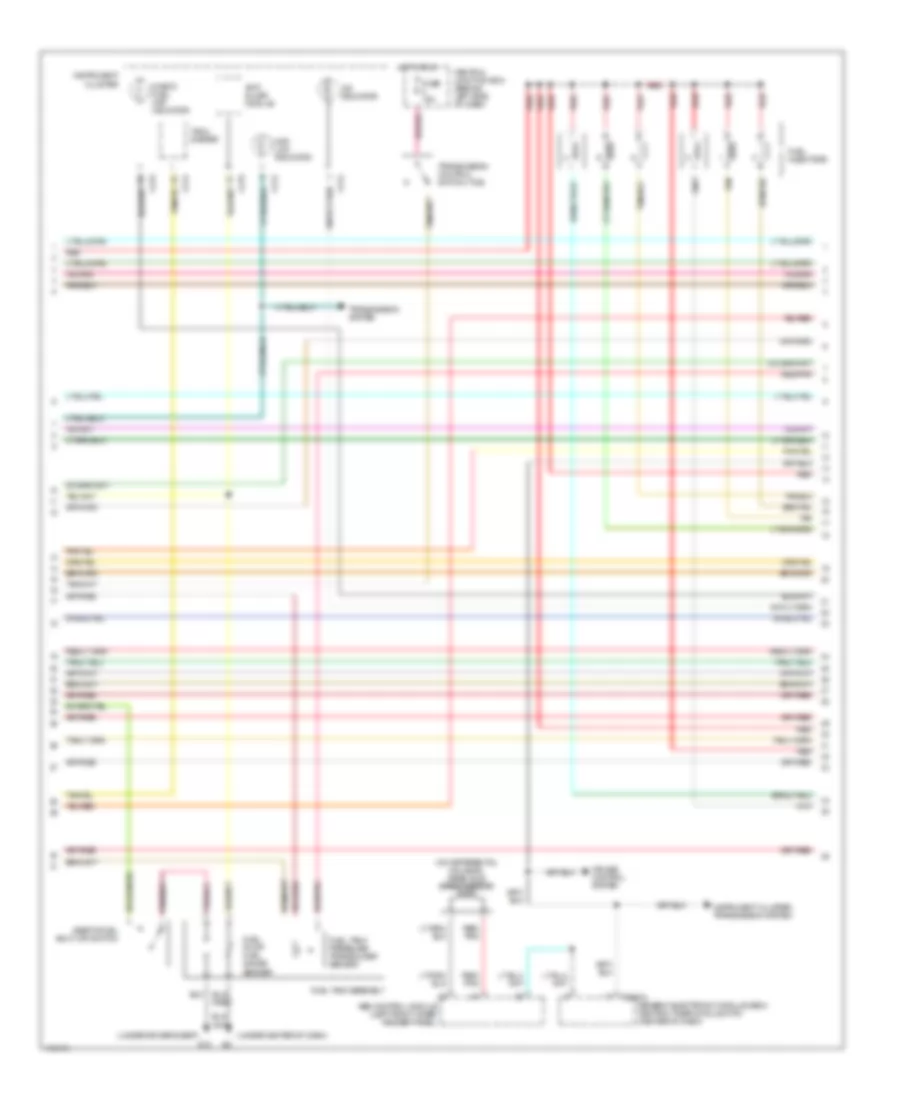
4.0L, Engine Performance Wiring Diagram (2 of 4) for Mazda B4000 Dual Sport 2003
 https://portal-diagnostov.com/license.html
Automotive Electricians Portal FZCO
Automotive Electricians Portal FZCO
https://portal-diagnostov.com/license.html
https://portal-diagnostov.com/license.html
Automotive Electricians Portal FZCO
Automotive Electricians Portal FZCOList of elements for 4.0L, Engine Performance Wiring Diagram (2 of 4) for Mazda B4000 Dual Sport 2003:
- (not used)
- A/c clutch relay
- A/t
- A/t
- Battery junction box (left rear of engine compartment)
- Clutch pedal position (cpp) switch (clutch pedal support)
- Engine coolant temperature (ect) sensor (top right of eng, near thermostat housing)
- Evap canister vent valve (behind left rear corner of vehicle)
- Evaporative emissions (evap) canister purge valve (left front of engine compt, near battery)
- Fuel pump relay
- Fuse 23 20a
- Fuse 41 20a
- Hot at all times
- Intermediate shaft speed sensor (left side of transmission)
- Knock sensor (on right side of engine)
- M/t
- M/t
- Mass airflow/ intake air temperature (iat) sensor (right side of engine compt, in air cleaner assembly)
- Output shaft speed sensor (left side of transmission)
- Red
- Throttle position (tp) sensor (on throttle body assembly)
4.0L, Engine Performance Wiring Diagram (3 of 4) for Mazda B4000 Dual Sport 2003
 https://portal-diagnostov.com/license.html
Automotive Electricians Portal FZCO
Automotive Electricians Portal FZCO
https://portal-diagnostov.com/license.html
https://portal-diagnostov.com/license.html
Automotive Electricians Portal FZCO
Automotive Electricians Portal FZCOList of elements for 4.0L, Engine Performance Wiring Diagram (3 of 4) for Mazda B4000 Dual Sport 2003:
- (on differential housing) rear axle speed sensor
- (under center of dash)
- (under driver's seat)
- 4wd low indicator
- Abs control module (left front inner fender panel)
- Anti- slosh module
- C214
- C215
- Central junction box (behind left side of dash)
- Check fuel cap indicator
- Cruise control system
- Fuel injectors
- Fuel pump/ fuel gauge sender
- Fuel tank assembly
- Fuel tank pressure transducer sensor
- Fuse 15a
- G10
- Generic electronic module (gem)/ central timer module (ctm) (center of dash)
- Hot in run
- Inertia fuel shut-off switch
- Instrument cluster
- Instrument cluster, transmission system
- O/d indicator
- Red
- Red/ pnk
- Red/pnk
- T2100a
- Tach- ometer
- Tan
- Transmission control switch (tcs)
- Transmission system
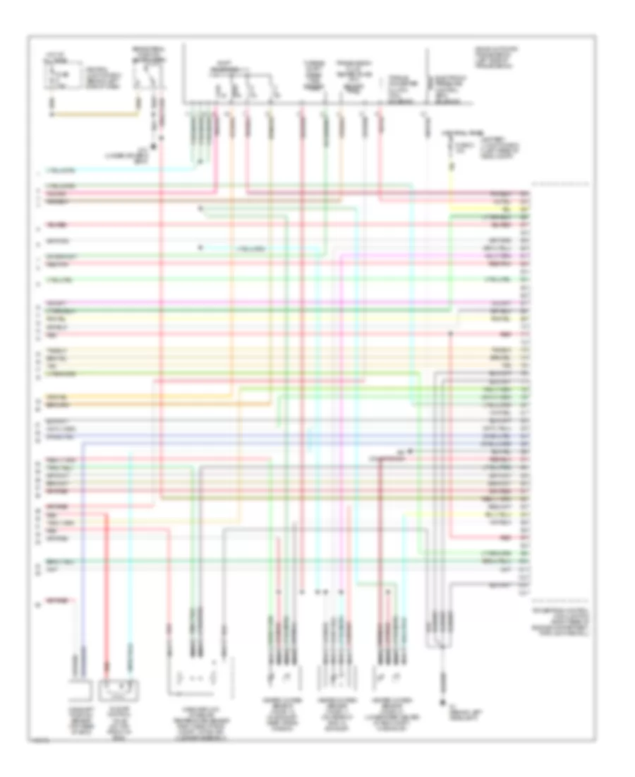
4.0L, Engine Performance Wiring Diagram (4 of 4) for Mazda B4000 Dual Sport 2003
 https://portal-diagnostov.com/license.html
Automotive Electricians Portal FZCO
Automotive Electricians Portal FZCO
https://portal-diagnostov.com/license.html
https://portal-diagnostov.com/license.html
Automotive Electricians Portal FZCO
Automotive Electricians Portal FZCOList of elements for 4.0L, Engine Performance Wiring Diagram (4 of 4) for Mazda B4000 Dual Sport 2003:
- 4r44e automatic transmission (left side of transmission)
- Air conditioning
- Battery junction box (left rear of eng compt)
- Brake pedal position switch (bpp)
- Camshaft position sensor (top rear of eng)
- Central junction box (behind left side of dash)
- Electronic pressure control (epc) solenoid
- Fuse 21 10a
- Fuse 7.5a
- G1 (behind left headlight)
- G10 (under driver's seat)
- Heated oxygen sensor (ho2s) 11 (on rear of eng, in exhaust)
- Heated oxygen sensor (ho2s) 12 (in exhaust, near trans- mission)
- Heated oxygen sensor (ho2s) 21 (lower rear center of eng compt, in exhaust)
- Hot at all times
- Idle air control valve (on top front of eng)
- Mass airflow/ intake air temperature sensor (right side of eng compt, within air cleaner assembly)
- Nca
- Powertrain control module (pcm) (right rear of engine compartment, through firewall)
- Red
- Red/pnk
- Shift solenoids
- Tan
- Torque converter clutch (tcc) solenoid
- Transmission fluid temperature (tft) sensor
- Turbine shaft speed (tss) sensor

 Čeština
 Dansk
Dansk Deutsch
 Ελληνικά
 English
 English
 Español
 Suomi
Suomi Français
 Français
 עברית
עברית Hrvatski
 Magyar
 Italiano
 한국어
한국어 Nederlands
 Polski
 Português
 Português
 Română
 Русский
 Slovenčina
 Slovenščina
 Svenska
 Türkçe
 中文 (中国)
