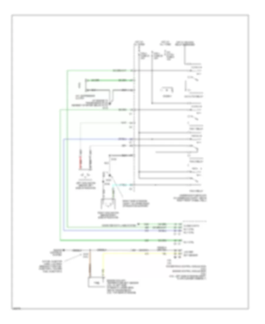
COOLING FAN
Cooling Fan Wiring Diagram for Chevrolet Uplander LT 2006
 https://portal-diagnostov.com/license.html
Automotive Electricians Portal FZCO
Automotive Electricians Portal FZCO
https://portal-diagnostov.com/license.html
https://portal-diagnostov.com/license.html
Automotive Electricians Portal FZCO
Automotive Electricians Portal FZCO
List of elements for Cooling Fan Wiring Diagram for Chevrolet Uplander LT 2006:
- (at engine to transmission stud nearest starter, below g113)
- (in fuel injector harn, 4 cm from breakout for fuel injector 2, toward fuel injector 3)
- (or 2761)
- (right side of engine compt, on upper front of radiator support)
- 3.5l
- 3.9l
- A/c compressor clutch
- A/c cltch fuse 6 10a
- A/c cltch relay
- Class 2 data
- Computer data lines system
- Diode 3
- Ect sensor
- Engine controls system
- Engine coolant temperature (ect) sensor (3.5l: in left side of rear cylinder head, above transmission) (3.9l: top rear of engine)
- Fan 1 fuse 29 30a
- Fan 1 relay
- Fan 2 fuse 33 40a
- Fan 2 relay
- Fan 3 relay
- G100
- G115
- Hot at all times
- Hot w/ ign main relay energized
- Left cooling fan (behind left side of radiator)
- Low ref
- Powertrain control module (pcm) (3.5l) engine control module (ecm) (3.9l) (3.5l: left side of engine compt, in air cleaner assembly)
- Red
- Right cooling fan (behind right side of radiator)
- Rly ctrl
- S102
- S106
- S140 (3.5l)
- Underhood fuse block (in underhood compt, above right front wheel well)
 Čeština
 Dansk
Dansk Deutsch
 Ελληνικά
 English
 English
 Español
 Suomi
Suomi Français
 Français
 עברית
עברית Hrvatski
 Magyar
 Italiano
 한국어
한국어 Nederlands
 Polski
 Português
 Português
 Română
 Русский
 Slovenčina
 Slovenščina
 Svenska
 Türkçe
 中文 (中国)
 日本語
日本語
