ENGINE PERFORMANCE
2.5L TURBO
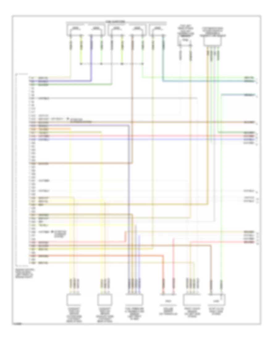
2.5L Turbo, Engine Performance Wiring Diagram (1 of 4) for Volvo C70 T-5 2006
 https://portal-diagnostov.com/license.html
Automotive Electricians Portal FZCO
Automotive Electricians Portal FZCO
https://portal-diagnostov.com/license.html
https://portal-diagnostov.com/license.html
Automotive Electricians Portal FZCO
Automotive Electricians Portal FZCO
List of elements for 2.5L Turbo, Engine Performance Wiring Diagram (1 of 4) for Volvo C70 T-5 2006:
- (a/t only)
- (top left rear of eng) coolant temperature sensor
- (top rear of eng) intake manifold pressure & temperature sensor
- A10
- A11
- A12
- A13
- A14
- A15
- A16
- A17
- A18
- A19
- A20
- A21
- A22
- A23
- A24
- A25
- A26
- A27
- A28
- A29
- A30
- A31
- A32
- A33
- A34
- A35
- A36
- A37
- A38
- A39
- A40
- A41
- A42
- A43
- A44
- A45
- A46
- A47
- A48
- A49
- A50
- A51
- A52
- A53
- A54
- A55
- Camshaft position sensor (exhaust side) (top right rear of eng)
- Camshaft position sensor (intake side) (top right rear of eng)
- Engine control module (ecm) (left front of engine compt)
- Evap valve (right side of eng)
- Front knock sensor (on left side of eng)
- Fuel injectors
- Fuel pressure & temperature sensor (left front of eng)
- Impulse sensor (on transaxle)
- Starting/ charging system
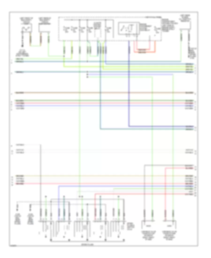
2.5L Turbo, Engine Performance Wiring Diagram (2 of 4) for Volvo C70 T-5 2006
 https://portal-diagnostov.com/license.html
Automotive Electricians Portal FZCO
Automotive Electricians Portal FZCO
https://portal-diagnostov.com/license.html
https://portal-diagnostov.com/license.html
Automotive Electricians Portal FZCO
Automotive Electricians Portal FZCOList of elements for 2.5L Turbo, Engine Performance Wiring Diagram (2 of 4) for Volvo C70 T-5 2006:
- (left front of eng compt) vacuum pump
- (left rear of eng compt) vacuum pump switch
- (left rear of eng) oil trap ptc resistor
- (top of eng, near spark plugs) 31/88
- 31/114 (on left macpherson strut tower)
- 31/88 (top of eng, near spark plugs)
- 31/89 (top of eng, near spark plugs)
- Climate control system relay
- Engine compartment distribution box (left side of engine compt, beside strut tower)
- Engine management system main relay
- Fuse 10a
- Fuse 15a
- Fuse 20a
- Fuse 30a
- Hot at all times
- Spark plugs
- Spark plugs & ignition coils
- Variable valve timing intake solenoid (right front of eng)
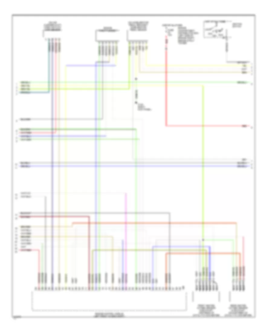
2.5L Turbo, Engine Performance Wiring Diagram (3 of 4) for Volvo C70 T-5 2006
 https://portal-diagnostov.com/license.html
Automotive Electricians Portal FZCO
Automotive Electricians Portal FZCO
https://portal-diagnostov.com/license.html
https://portal-diagnostov.com/license.html
Automotive Electricians Portal FZCO
Automotive Electricians Portal FZCOList of elements for 2.5L Turbo, Engine Performance Wiring Diagram (3 of 4) for Volvo C70 T-5 2006:
- (on accelerator pedal bracket) accelerator pedal sensor
- (on air cleaner duct) mass air flow (maf) sensor
- 31/84 (right kick panel)
- Acc
- Engine compartment distribution box (left side of engine compt, beside strut tower)
- Engine control module (left front of eng compt)
- Engine throttle body
- Front heated oxygen sensor (in exhaust, upstream of catalytic converter)
- Fuse 10a
- Hot at all times
- Ignition switch
- Lock
- Nca
- Off
- Rear heated oxygen sensor (in exhaust, downstream of catalytic converter)
- Red
- Run
- Start
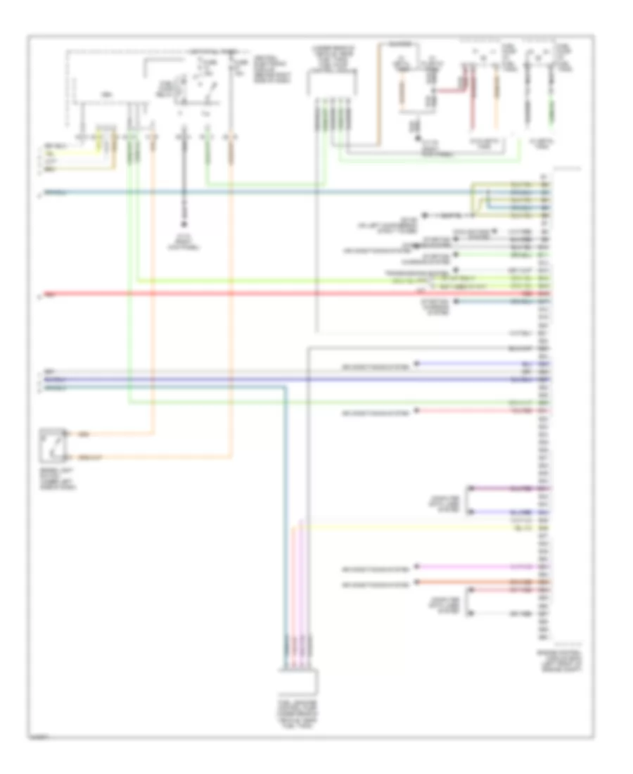
2.5L Turbo, Engine Performance Wiring Diagram (4 of 4) for Volvo C70 T-5 2006
 https://portal-diagnostov.com/license.html
Automotive Electricians Portal FZCO
Automotive Electricians Portal FZCO
https://portal-diagnostov.com/license.html
https://portal-diagnostov.com/license.html
Automotive Electricians Portal FZCO
Automotive Electricians Portal FZCOList of elements for 2.5L Turbo, Engine Performance Wiring Diagram (4 of 4) for Volvo C70 T-5 2006:
- ( w/ a/t only)
- (not used w/ a/t)
- (under rear of vehicle, near fuel tank) fuel pump control module
- 31/10 (right kick panel)
- 31/116 (right kick panel)
- A/t
- Air conditioning system
- B10
- B11
- B12
- B13
- B14
- B15
- B16
- B17
- B18
- B19
- B20
- B21
- B22
- B23
- B24
- B25
- B26
- B27
- B28
- B29
- B30
- B31
- B32
- B33
- B34
- B35
- B36
- B37
- B38
- B39
- B40
- B41
- B42
- B43
- B44
- B45
- B46
- B47
- B48
- B49
- B50
- B51
- B52
- B53
- B54
- B55
- B56
- B57
- B58
- B59
- B60
- Brake light switch (under left side of dash)
- Cem
- Central electronic module (behind right side of dash)
- Computer data lines system
- Cooling fans system
- Engine control module (ecm) (left front of engine compt)
- Fuel leakage control pump (under rear of vehicle, near fuel tank)
- Fuel pump (in fuel tank)
- Fuel pump relay
- Fuse 15a
- G31/52 (on left macpherson strut tower)
- Hot at all times
- M/t
- Nca
- Red
- Starting/ charging system
- Transmissions system
- W/ metal tank
- W/ plastic tank

 Čeština
 Dansk
Dansk Deutsch
 Ελληνικά
 English
 English
 Español
 Suomi
Suomi Français
 Français
 עברית
עברית Hrvatski
 Magyar
 Italiano
 한국어
한국어 Nederlands
 Polski
 Português
 Português
 Română
 Русский
 Slovenčina
 Slovenščina
 Svenska
 Türkçe
 中文 (中国)
