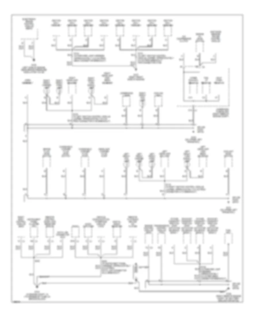
GROUND DISTRIBUTION
Ground Distribution Wiring Diagram (1 of 3) for Cadillac XLR 2005
 https://portal-diagnostov.com/license.html
Automotive Electricians Portal FZCO
Automotive Electricians Portal FZCO
https://portal-diagnostov.com/license.html
https://portal-diagnostov.com/license.html
Automotive Electricians Portal FZCO
Automotive Electricians Portal FZCO
List of elements for Ground Distribution Wiring Diagram (1 of 3) for Cadillac XLR 2005:
- A c1
- A/c compressor clutch
- A9 c1
- Audio amplifier
- Battery
- Brake fluid level switch
- C10
- Coolant level switch
- Cooling fan
- Data link connector (dlc)
- Digital radio receiver
- Distance sensing cruise control module
- E16 c1
- Electronic brake control module (ebcm)
- Engine control module (ecm)
- Engine oil level switch
- Exhaust camshaft position (cmp) actuator solenoid- bank 1
- Exhaust camshaft position (cmp) actuator solenoid- bank 2
- Fog lp relay 38
- Fuel rail
- G101 (on upper left frame rail)
- G102 (on upper left frame rail)
- G104 (in engine compt, in i/p harness by fuse un erhood block)
- G105 (left side of engine, near brake pressure modulator valve)
- G106 (right rear of engine compt, by battery, ground for sp106)
- G107 (right front side of engine)
- Hdlp wash relay 46
- Headlamp washer fluid pump
- Horn assembly
- Ignition coil/ module 1
- Ignition coil/ module 2
- Ignition coil/ module 3
- Ignition coil/ module 4
- Ignition coil/ module 5
- Ignition coil/ module 6
- Ignition coil/ module 7
- Ignition coil/ module 8
- Instrument panel cluster (ipc)
- Intake camshaft position (cmp) actuator solenoid- bank 1
- Intake camshaft position (cmp) actuator solenoid- bank 2
- Left front fog lamp
- Left front marker lamp
- Left front park lamp
- Left front turn signal lamp
- Left headlamp ballast
- Left headlamp high beam solenoid
- M14
- Radio
- Remote control door lock receiver (rcdlr)
- Remote playback device- cd player
- Right body control module (bcm)
- Right front fog lamp
- Right front marker lamp
- Right front park lamp
- Right front turn signal lamp
- Right headlamp ballast
- Right headlamp high beam solenoid
- S133 (in left ignition control module jumper, approximately 5.0 cm from breakout for connector c109)
- S144 (in forward lamp harness, approximately 12.5 cm from ebcm connector breakout)
- S230 (in instrument panel harness, approximately 6.5 cm from data link connector (dlc) breakout)
- S232
- Splice pack sp101
- Splice pack sp102
- Splice pack sp106
- Transmission control module (tcm)
- Underhood fuse block (right rear of engine compt)
- Underhood lamp
- Vehicle communication interface module (vcim)
- Windshield washer fluid level switch
- Windshield washer fluid pump
- Wiper run/acc relay 42
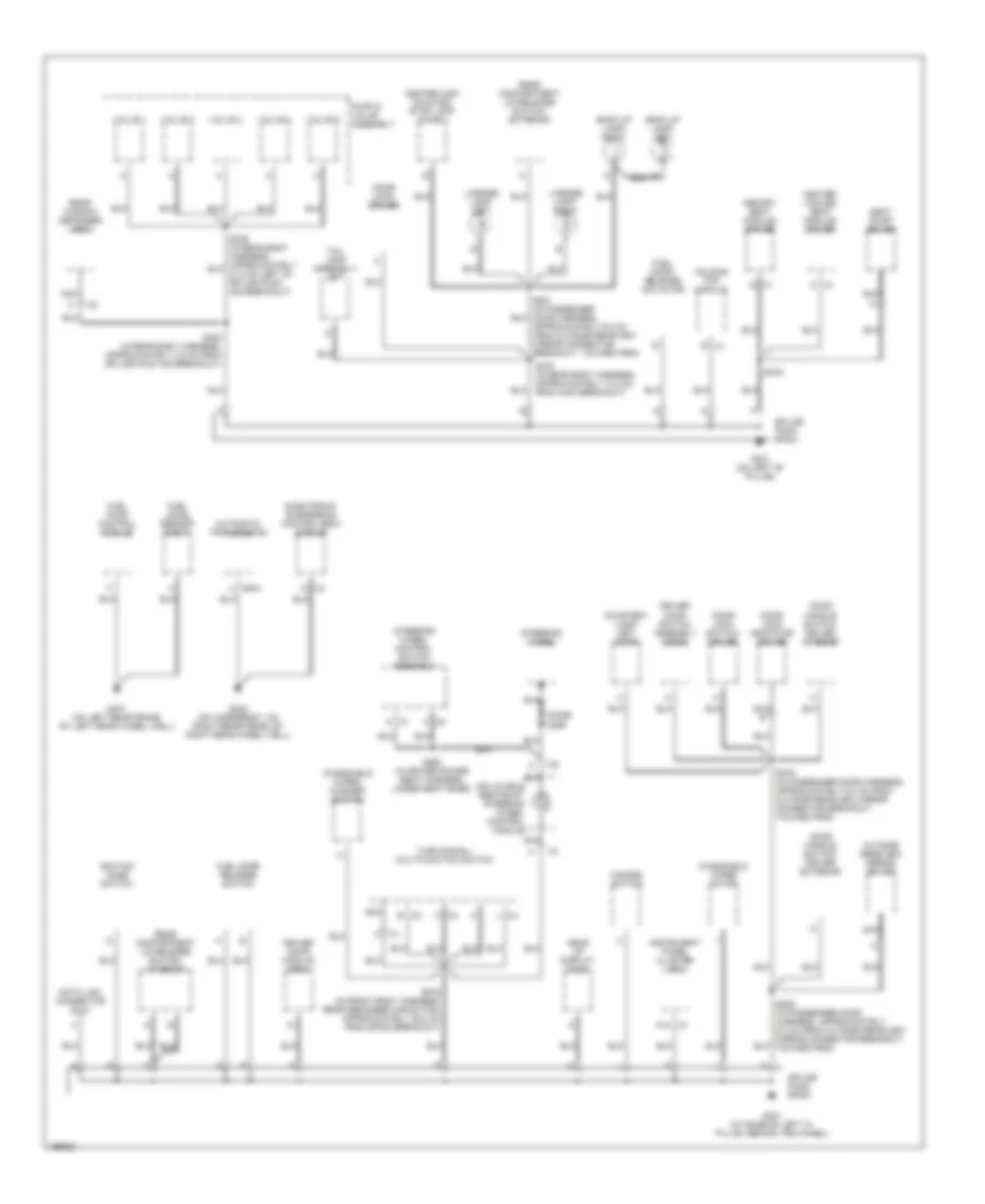
Ground Distribution Wiring Diagram (2 of 3) for Cadillac XLR 2005
 https://portal-diagnostov.com/license.html
Automotive Electricians Portal FZCO
Automotive Electricians Portal FZCO
https://portal-diagnostov.com/license.html
https://portal-diagnostov.com/license.html
Automotive Electricians Portal FZCO
Automotive Electricians Portal FZCOList of elements for Ground Distribution Wiring Diagram (2 of 3) for Cadillac XLR 2005:
- A10 c1
- Automatic transmission
- B c1
- B c2
- Back up lamp- left
- Back up lamp- right
- C c1
- C400
- Center high mounted stop lamp (chmsl)
- Courtesy lamp- left door
- D c3
- Data link connector (dlc)
- Diode d295
- Door handle switch- driver exterior
- Door handle switch- driver interior
- Door lock indicator- driver
- Door lock switch- driver
- Door lock- driver
- Driver door module (ddm)
- Driver door switch assembly (ddsa)
- Electronic suspension control (esc) module
- Folding top module
- Fuel door release actuator
- Fuel door release switch
- Fuel level sensor- right
- Fuel pump control module
- G201 (at base of left "a" pillar, behind trim panel)
- G301 (on left "b" pillar)
- G401 (on left rear frame, by left rear wheel well)
- G402 (on underbody, on right rear frame, by right rear wheel well)
- Hazard switch
- Head up display (hud)
- Heated/ cooled seat module- driver
- Ignition mode switch
- Inflatable restraint steering wheel control module
- Instrument panel cluster (ipc)
- J c4
- K c3
- License lamp- left
- License lamp- right
- Memory seat module- driver
- Nca
- Nca b
- Outside rearview mirror- driver
- Pump & valve assembly
- Rear compartment lid release switch- exterior
- Rear compartment lid release switch- interior
- Rear window defogger grid
- S275 (in front body harness, rear defogger capacitor, approximately 20.0 cm from sp302 breakout)
- S293 (in driver power seat harness, under seat base)
- S335 (in rear body harness, approximately 3.5 cm from splice pack 400 breakout)
- S375 (in rear body harness, approximately 13.0 cm from c400 breakout)
- S379
- S579 (in passenger door harness, approximately 6.0 cm from outside rearview mirror connector breakout, toward p600)
- S931 (in passenger door harness, approximately 6.0 cm from outside rearview mirror connector breakout, toward p600)
- Seat pump- driver
- Splice pack sp201
- Splice pack sp301
- Steering wheel
- Steering wheel control switch assembly
- Tail lamp assembly- left
- Turn signal/ multifunction switch
- Valve 1
- Valve 2
- Valve 3
- Valve 4
- Valve 5
- Windshield wiper motor
- Windshield wiper/ washer switch
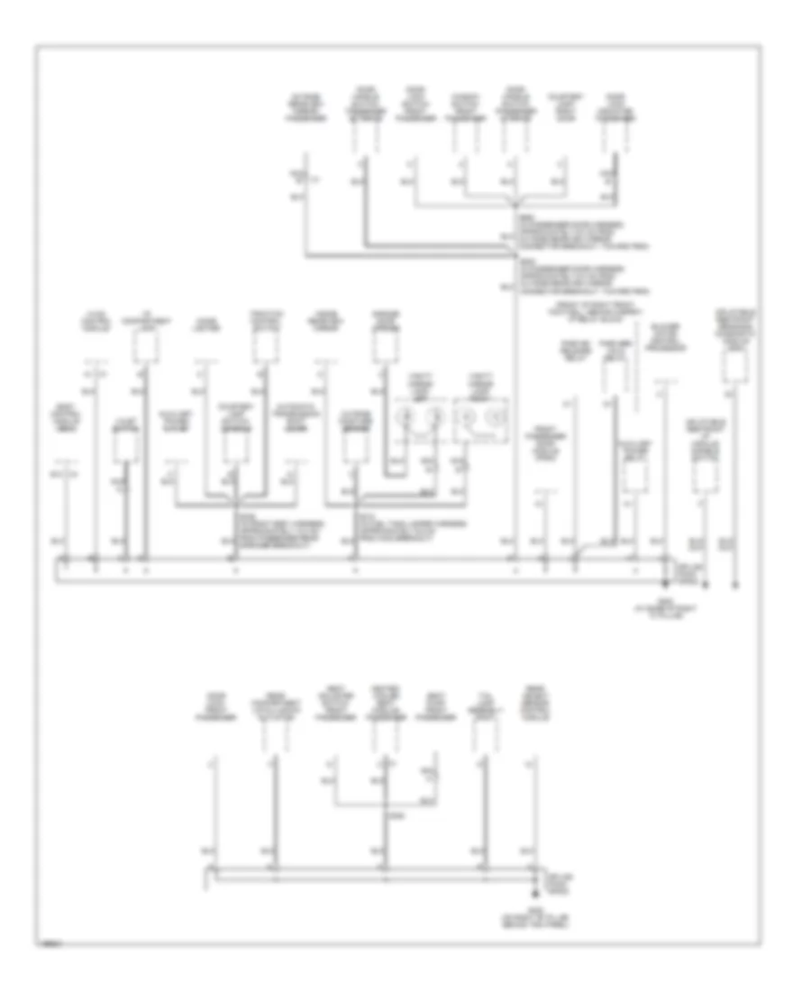
Ground Distribution Wiring Diagram (3 of 3) for Cadillac XLR 2005
 https://portal-diagnostov.com/license.html
Automotive Electricians Portal FZCO
Automotive Electricians Portal FZCO
https://portal-diagnostov.com/license.html
https://portal-diagnostov.com/license.html
Automotive Electricians Portal FZCO
Automotive Electricians Portal FZCOList of elements for Ground Distribution Wiring Diagram (3 of 3) for Cadillac XLR 2005:
- (front of right front footwell, behind carpet) i/p relay block
- Automatic transmission shift lever
- Auxiliary power outlet
- Auxiliary power relay
- Blower motor control processor
- Body control module (bcm)
- C1 a1
- C1 c
- C4 e12
- Cigar lighter
- Connector breakout, toward p600)
- Courtesy lamp switch- console
- Courtesy lamp- right door
- Door handle switch- passenger exterior
- Door handle switch- passenger interior
- Door lock indicator- passenger
- Door lock switch- front passenger
- Door lock- front passenger
- Front passenger door module (fpdm)
- G202 (at base of right "a" pillar)
- G302 (on right "b" pillar, behind trim panel)
- Garage door opener
- Heated/ cooled seat module- passenger
- Hvac control module
- I/p compartment lamp
- Inflatable restraint i/p module disable switch
- Inflatable restraint sensing & diagnostic module (sdm)
- Inside rearview mirror
- Nca
- Nca b
- Outside moisture sensor
- Outside rearview mirror- passenger
- Park bk release relay
- Park brk hold relay
- Rear compartment lid pulldown actuator
- Rear object sensor control module
- S382
- Seat adjuster switch- front passenger
- Seat pump- front passenger
- Splice pack sp202
- Splice pack sp302
- Tail lamp assembly- right
- Traction control switch
- Valet switch
- Vanity mirror lamp- left
- Vanity mirror lamp- right
- Window switch- front passenger

 Čeština
 Dansk
Dansk Deutsch
 Ελληνικά
 English
 English
 Español
 Suomi
Suomi Français
 Français
 עברית
עברית Hrvatski
 Magyar
 Italiano
 日本語
日本語 Nederlands
 Polski
 Português
 Português
 Română
 Русский
 Slovenčina
 Slovenščina
 Svenska
 Türkçe
 中文 (中国)
