POWER DISTRIBUTION
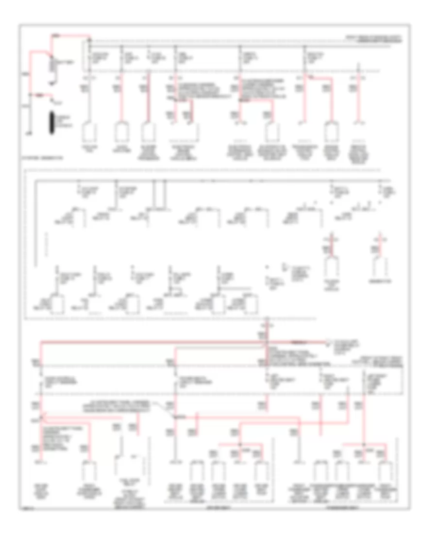
Power Distribution Wiring Diagram (1 of 4) for Cadillac XLR 2005
 https://portal-diagnostov.com/license.html
Automotive Electricians Portal FZCO
Automotive Electricians Portal FZCO
https://portal-diagnostov.com/license.html
https://portal-diagnostov.com/license.html
Automotive Electricians Portal FZCO
Automotive Electricians Portal FZCO
List of elements for Power Distribution Wiring Diagram (1 of 4) for Cadillac XLR 2005:
- (front of right front footwell, behind carpet) i/p relay block
- (in instrument panel harness, approximately 32.5 cm (12.7 in)
- (in instrument panel harness, approximately 39.5 cm (15.5 in) from inside rearview mirror breakout)
- (right rear of engine compt) underhood fuse block
- A c1
- A/c comp fuse 15 10a
- A/c comp relay 35
- A18
- A19
- A2 c2
- A2 c4
- Abs fuse 27 60a
- Amp fuse 31 30a
- Audio amplifier
- B c3
- B1 c4
- Batt 1 fuse 33 60a
- Batt 2 fuse 29 40a
- Battery
- Blower motor control processor
- C14
- C2 c1
- Coolfan fuse 32 40a
- Cooling fan
- Crank relay 43
- D c1
- D11
- D11 c3
- Door controls circuit breaker 30a
- Driver door module (ddm)
- Driver heated/ cooled seat module
- Driver lower lumbar switch
- Driver memory seat module
- Driver seat
- Driver seat pump
- Driver upper lumbar switch
- Ecm/tcm fuse 11 15a
- Electronic brake control module (ebcm)
- Electronic suspension control (esc) module
- Engine control module (ecm)
- Evaporative emission (evap) canister vent solenoid
- F12 c3
- Fog lp fuse 22 15a
- Fog lp relay 38
- Folding top module
- Front passenger door module (fpdm)
- Front passenger seat adjuster switch
- Front passenger seat pump
- Fuel door relay
- Generator
- H c1
- H13
- H14
- Hdlp wash fuse 18 20a
- Hdlp wash relay 46
- High beam relay 39
- Horn fuse 2 15a
- Horn relay 34
- Hvac control head connector)
- Hvac fuse 28 40a
- I/p relay block (front of right front footwell, behind carpet)
- Ign 1 relay 44
- K10
- K14
- Left heated seat fuse 15a
- Left/right power lumbar fuse 15a
- Low beam relay 47
- Mrrtd fuse 13 25a
- Nca
- Park lamp relay 37
- Passenger heated/ cooled seat module
- Passenger lower lumbar switch
- Passenger seat
- Passenger upper lumbar switch
- Pk lamps fuse 8 10a
- Power seats circuit breaker 30a
- Rear defog relay 4
- Red
- Remote control door lock receiver (rcdlr)
- Right heated seat fuse 15a
- S137
- S224
- S234
- Starter
- Starter fuse 30 40a
- To auxiliary power relay (diagram 3 of 4)
- To batt 3 fuse 26 (diagram 2 of 4)
- Transmission control module (tcm)
- W/s wash fuse 17 15a
- W/s wash relay 36
- Wiper fuse 4 30a
- Wiper on/off relay 45
- Wiper run/acc relay 42
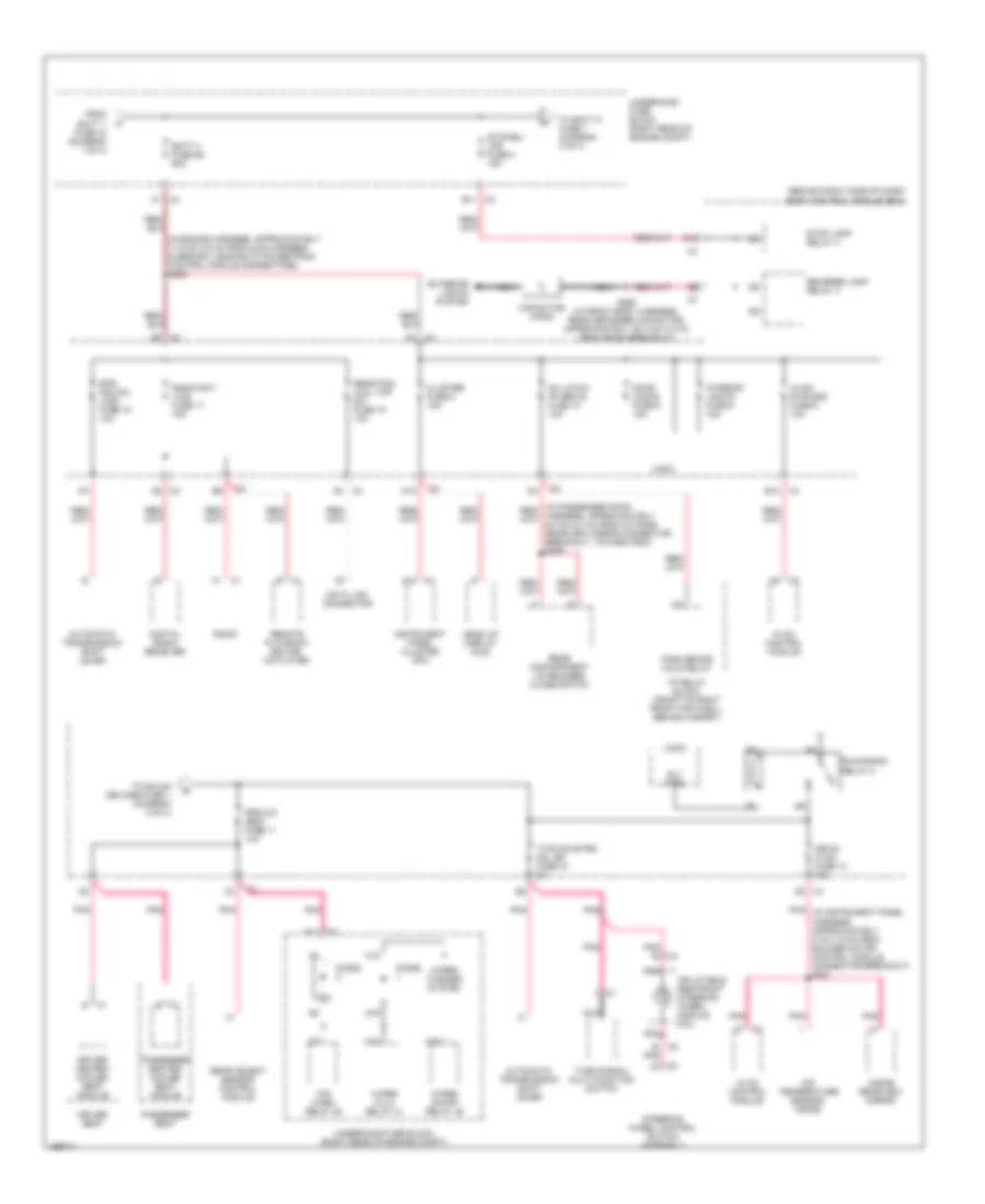
Power Distribution Wiring Diagram (2 of 4) for Cadillac XLR 2005
 https://portal-diagnostov.com/license.html
Automotive Electricians Portal FZCO
Automotive Electricians Portal FZCO
https://portal-diagnostov.com/license.html
https://portal-diagnostov.com/license.html
Automotive Electricians Portal FZCO
Automotive Electricians Portal FZCOList of elements for Power Distribution Wiring Diagram (2 of 4) for Cadillac XLR 2005:
- (behind right side of dash) body control module (bcm)
- A12 c1
- A6 c3
- A7 c2
- A8 c2
- A8 c3
- Ac latch/ pk brk b fuse 10 10a
- Air temperature sensor- inside
- Automatic transmission shift lever
- B c1
- B c5
- B11 c3
- Batt 3 fuse 26 60a
- Btsi sol/col lock fuse 19 10a
- C1 c4
- Capacitor cp200
- Cluster fuse 8 15a
- D1 c3
- D10
- D6 c3
- D8 c4
- Data link connector
- Digital radio receiver
- Diode
- Door locks fuse 5 15a
- Driver heated/ cooled seat module
- Driver seat
- E10 c4
- E11 c3
- Exterior lights system
- F1 c1
- F19
- From batt 1 fuse 33 (diagram 1 of 4)
- G19
- Head up display (hud)
- Hvac control module
- Hvac/ pwr snd fuse 9 10a
- I/p relay block (front of right front footwell, behind carpet)
- Inflatable restraint steering wheel module coil
- Inside rearview mirror
- Instrument panel cluster (ipc)
- Interior lights fuse 6 10a
- Isrvm/ hvac fuse 14 10a
- Logic
- M10
- M18
- Nca
- Park brake hold relay
- Passenger heated/ cooled seat module
- Passenger seat
- Pnk
- Pnk (in instrument panel harness, approximately 5 cm (1.9 in) from blower motor control module connector breakout) s231
- Pnk b c4
- Radio
- Radio/ant/ vics fuse 17 15a
- Rear compartment lid release/ close switch
- Rear fog/ aldl top sw fuse 18 10a
- Rear object sensor control module
- Remote playback device- cd player
- Reverse lamp relay 3
- Rly ctrl
- Rpa/h/c/ seat fuse 11 10a
- Run/crank relay 2
- S260 (in front body harness, rear defogger capacitor, approximately 20.0 cm (7.8 in) from sp302 breakout)
- Steering wheel control switch assembly
- Stop lamp relay 4
- Stop/bu/ lps fuse 5 15a
- To batt 5 fuse 7 (diagram 3 of 4)
- To gmlan devices fuse 1 (diagram 3 of 4)
- Turn signal/ multi-function switch
- Tutd sw/strg col sw fuse 15 2a
- Underhood fuse block (right rear of engine compt)
- W/s wash relay 36
- Wiper hi/lo relay 41
- Wiper on/off relay 45
- Wiper/ washer system
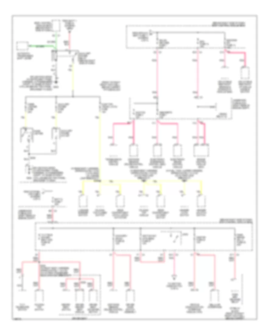
Power Distribution Wiring Diagram (3 of 4) for Cadillac XLR 2005
 https://portal-diagnostov.com/license.html
Automotive Electricians Portal FZCO
Automotive Electricians Portal FZCO
https://portal-diagnostov.com/license.html
https://portal-diagnostov.com/license.html
Automotive Electricians Portal FZCO
Automotive Electricians Portal FZCOList of elements for Power Distribution Wiring Diagram (3 of 4) for Cadillac XLR 2005:
- (behind right side of dash) body control module (bcm)
- (front of right front footwell, behind carpet) i/p fuse block
- (in fuel tank jumper harness, approximately 81.5 cm (32 in) from c408 breakout) s319
- (in rear body harness, approximately 5 cm (1.9 in) from lr license lamp breakout) s355
- (in rear body harness, approximately 6.5 cm (2.5 in) from c400 breakout) s333
- Abs/mrrtd fuse 1 10a
- Acc/tcm fuse 3 10a
- Acca/driv dr sw fuse 25 10a
- Automatic transmission shift lever
- Auxiliary power fuse 20a
- Auxiliary power outlet
- Auxiliary power relay (behind right side of dash)
- B10 c4
- B12 c3
- B5 c3
- Batt 5 fuse 7 30a
- Body control module (bcm) (behind right side of dash)
- C10
- C13
- C5 c3
- Cellular microphone
- Cigar lighter
- Cigar lighter fuse 20a
- Crank relay 43
- D11
- D11 c3
- D12
- Distance sensing cruise control module
- Driver door switch assembly
- Driver memory seat module
- Driver seat
- Driver seat adjuster switch
- E11
- Ecm fuse 12 15a
- Electronic brake control module
- Electronic suspension control (esc) module
- Engine control module (ecm)
- F1 c4
- F10
- F11
- F11 c2
- Fldg top/ trunk latch fuse 15a
- Folding top closed switch
- Folding top module
- Folding top switch
- From batt 1 fuse 33 (diagram 1 of 4)
- From rpa/h/c/ d seat fuse 11 (diagram 2 of 4)
- From stop/bu/ c lps fuse 5 (diagram 2 of 4)
- G202
- Gmlan devices fuse 1 20a
- Header latch switch
- Header unlatch switch
- I/p relay block (front of right front footwell, behind carpet)
- Ignition sw/ intr sens fuse 27 10a
- Inflatable restraint i/p module disable switch
- Inflatable restraint sensing & diagnostic module (sdm)
- Logic
- Luggage barrier switch
- Memory seat switch
- Nca
- Onstar fuse 24 10a
- Park brake sol a fuse 23 20a
- Park brk release relay
- Pnk
- Rear compartment lid open switch
- Rear compartment lid pulldown actuator
- S248 (in front body harness, approximately 15.0 cm (5.9 in) from passenger rear speaker breakout)
- Sdm/psir sw fuse 13 10a
- Splice pack sp202 (in instrument panel harness, in passengers compt, at base of right a pillar behind trim panel, grounded to g202)
- Tilt/ telescope switch
- Tilt/tele sw/mem seat mod fuse 26 10a
- To ignition mode switch (4 of 4)
- Transmission control module
- Underhood fuse block (right rear of engine compt)
- Vehicle communication interface module (vcim)
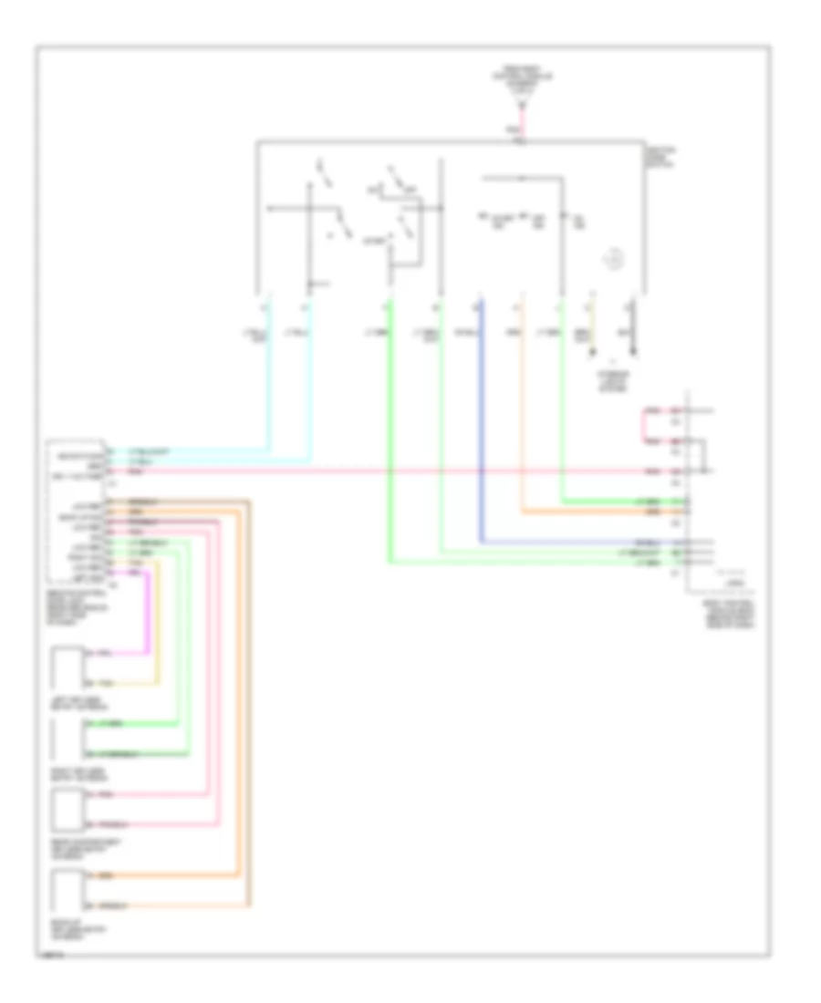
Power Distribution Wiring Diagram (4 of 4) for Cadillac XLR 2005
 https://portal-diagnostov.com/license.html
Automotive Electricians Portal FZCO
Automotive Electricians Portal FZCO
https://portal-diagnostov.com/license.html
https://portal-diagnostov.com/license.html
Automotive Electricians Portal FZCO
Automotive Electricians Portal FZCOList of elements for Power Distribution Wiring Diagram (4 of 4) for Cadillac XLR 2005:
- Back up sig
- Back-up keyless entry antenna
- Body control module (bcm) (behind right side of dash)
- From body control module (diagram 3 of 4)
- Grd
- Ign 1 voltage
- Ign data sig
- Ignition mode switch
- Interior lights system
- Left keyless entry antenna
- Left sig
- Logic
- Low ref
- Off
- Off ind
- On ind
- Pnk
- Rear compartment keyless entry antenna
- Remote control door lock receiver (rcdlr) (right side of dash)
- Right keyless entry antenna
- Right sig
- Sig
- Start
- Start ind
- Tan

 Čeština
 Dansk
Dansk Deutsch
 Ελληνικά
 English
 English
 Español
 Suomi
Suomi Français
 Français
 עברית
עברית Hrvatski
 Magyar
 Italiano
 日本語
日本語 Nederlands
 Polski
 Português
 Português
 Română
 Русский
 Slovenčina
 Slovenščina
 Svenska
 Türkçe
 中文 (中国)
